John's homebrew page

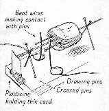
My interest in electronics goes a long way back - I think the Ladybird book "Magnets, Bulbs and Batteries" was one of my earliest tutors; that had me hunting for double cotton covered wire at the time when it was becoming difficult to get. I remember making a working electric motor from a cork, a darning needle, two short pins, four long needles, two drawing pins, a magnet, some DCC wire, and a battery. Very satisfying - I found my old book and here it is (the horseshoe magnet goes over the top) ...

Magnets, Bulbs and Batteries motor

For real electronics I was lucky enough to be given a "Phillips Electronic Engineer" kit for Christmas in 1964 (I think). This enabled me to build a real transistor radio - but also gave me the components to experiment with.

Current project - Microwaves - VHF/UHF - HF - Miscellaneous - Old projects

Current project - 13cm (2.3GHz) transverter

The local oscillator of the 13cm transverter is complete and working, so the next step is to build the main board.

For the design there were a few new ideas I wanted to try. First, commercial passive double balanced mixers for the microwave region are expensive, whereas I had found some IC mixers costing just a pound or two each. That was clearly an idea worth trying. Secondly, I needed some selectivity at 2.3GHz, and commercial helical filters are also rather expensive; so I thought I'd try some stripline tuned circuits (and pipe cap filters are another definite possibility).

I also had quite a lot of A06 and A03 MMICs on surplus boards from commercial equipment, so thought I'd make use of what I have there as well. With these design ideas in mind, I drew up a circuit using the gEDA Schematic Editor.

Here's the PCB after etching; my most successful optically produced PCB so far!

part populated board

With the receive and transmit sections soldered up, I have been doing a few tests. From home this was not very successful. Here's the test setup outdoors; the transverter board still isn't boxed so it's rather a lash-up.

Rx test setup

I'd set up for a Tuesday evening SHF (2.3GHz and up) activity contest, but heard no-one. I'm not surprised, my home location is far from ideal for microwaves, with a clearish direction only to the north. However, with my home brew 12 element DL6WU Yagi (still to be written up) I was able to detect RF "mush" from a communications mast about 2km away, and also my little mini beacon (just a 25.1750 MHz block oscillator with a 30mm bit of wire attached to the output pin; I detect the 92nd harmonic in the 13cm band!) was detectable from the garden. Here's the antenna:

Rx test setup

The antenna certainly seems to behave very well indeed, and it will be great for /P operation.

Having failed to detect any amateur signals, I decided that I should go somewhere I would have an excellent chance of doing that, providing the receiver was working as I hoped. So I set out for Cairnpapple Hill in West Lothian, which is line of sight to the GB3CSB beacon cluster. Once the test setup was assembled, I could hear the 13cm beacon easily - even before the antenna was pointing at it. In fact, I could hear it without an antenna! (Since the transverter still isn't boxed.) With the antenna pointing at the beacon, there was a very strong signal indeed - S9+.

The beacon tone was absolutely clear (very musical in fact with the JT4G signal alternating with the CW), so there are not going to be noise problems resulting from my use of a PLL/synthesiser local oscillator. In fact, the 20MHz TCXO reference oscillator I have used seems to be very stable and also very accurate; the beacon frequency indicated on the FT-817 was only about 60Hz out, not bad at 2320MHz!

The next step was to finish the transmit side, then put the whole thing in a box. The transmit side seems to be a little more problematic than the receive side; it seems that the filters have rather more loss than I'd expected, since the output level is not at all as high as I'd hoped. However, given large filter losses (6dB in each?) the observed output (which might be as much as 0dBm!) is not too surprising, given the MMIC combination I'm using. So I decided to go ahead, box it up, and add the PA (a salvaged commercial board which should have 40-43dB gain!) to see if it works.

Here's the underside of the main board, with the ends added to take SMA connectors, and screws in the regulators to bolt them to the sub-chassis for cooling.

Main board ground side

Here are the circuit diagrams. First, the power switching which is on-board:

power switching circuit

Next, the receive side of the transverter. I forgot to change the grey background on this one!

receive circuit

Finally the transmit side:

transmit circuit

The bottom of the box has the sequencer board (controlled by a PIC - details will follow eventually), the coaxial relay (obtained at a rally) and space for the PA board. There will eventually also be a bandpass filter between the antenna relay and the antenna N connector. A heat sink bolts to the other side of this chassis under the PA board.

Assembly - bottom level

The main transverter board and LO are mounted on a sub-chassis; this makes for a more compact overall system than my mark 2 23cm transverter. I didn't know at this stage whether or not I needed a lid on the main board box.

Assembly - top level

Under test, with the PA board added, I found that the system took off (oscillations) under transmit, even on SSB, with the main board open. A bit of anti-static foam over the box stopped that for low levels of drive but not higher levels; and with the main box lid on it was not stable at all on transmit.

Here's a photo of the system under test. You can see the anti-static foam just placed over the transverter board box. The bench could be tidier!

Under test

I made a proper tinplate lid for the main board box, and that cured the oscillations completely with the overall box lid off, so I felt we were ready for some on-air tests.

The monthly RSGB UKAC for SHF was due, so I went out to a local hill (the Braid Hills) which is easy to access and gives me a much better location than at home. This turned out to be really successful; I could even hear the GB3CSB beacon, and had four good contacts over 40 minutes (I tend to chat!) including 93km to Jon GM4JTJ, with some good signal reports. I thought this was not bad for probably 4 Watts (as estimated from the DC power input to the final stage and the device efficiency) and a 12 element Yagi.

The next steps were firstly, to put in a proper screened output N connector (which unfortunately made no difference!), then secondly to box in the PA board, to try to stabilise the whole system under transmit. I made up a screening box from tinplate which fits between the box base and within a few millimetres of the sub-chassis; it fits tightly round the PA board. It's a bit rough but I was in a hurry!

PA screening box

Here's the screening box fitted around the (surplus commercial) PA board. I was quite surprised and absolutely delighted when I reassembled the system with the sub-chassis to find that the unwanted oscillations had all gone away; I can now operate the transverter with the overall lid in place. I thought that I might need to add some braid around the bottom of the screening box, to make a better contact with the box floor, and to add a proper lid. I was even prepared to add absorbing foam inside the screening box! However these steps proved not to be needed.

PA boxed in

So here's the whole transverter with the lid on. It still needs some rubber feet! The two power connectors allow two external 12V batteries to provide both 12V and 24V easily.

completed transverter

I still want to add a bandpass filter of some sort, and the transverter would probably benefit from being tuned up again now all the lids are done, but it works and gives me a few Watts on 2.3GHz. I'm ready to take it out on the next RSGB SHF UKAC now! 

That's pretty well the end of the project - I'll add anything further if and when it happens. Down the line I would like to build my own PA board but that's really a separate project.

Microwave projects

VHF/UHF projects

HF projects

Miscellaneous stuff

Recent projects in calendar order

There are also a few new things that aren't written up yet - I've nearly finished a 2m portable (!) dish antenna for 23cm (and possibly 13cm); I've finally got round to making optically produced PCBs for tiny SMD components; and I've been playing a bit with QRSS on HF. Notes on these will appear eventually.

This list is growing reasonably rapidly - here are the recent projects (most recent first):

2010

2009

Old projects

The old projects are described on a separate page; they include all sorts of stuff, from my first (valve) oscilloscope to my first computer, programmed with a screwdriver, and a telephone modem.