
John's homebrew pages
A single board 23cm (1.3GHz) transverter with 144MHz IF
As I have gradually built up a bit of experience in the microwave
bands, I have been thinking about a nice project which could help a
lot of other people to get going quite easily, fairly quickly, and
most importanly (for me!) cheaply.
There are quite a few designs for transverters for 1.3GHz / 23cm on
the web. Very early on I came across this
design by Rick Cambell KK7B which was a great inspiration and
stimulus to getting going myself on 1.3GHz - it showed that it could
be done easily. I ended up with transverters that had to be tuned
(Rick's is a no-tune design with printed filters) but even that
wasn't too hard in the end. I also found the designs
by Paul Wade W1GHZ very inspiring.
However, these designs are not truly single board - they need an
external local oscillator, which is the really key component in a
transverter. My recent experiments on 2.3GHz
and 10GHz have
led me to the use of synthesised local oscillators, stabilised by
tiny temperature compensated crystal oscillator (TCXO) modules.
These have been working very well indeed for me; they are very
compact, and so I thought I would try to incorporate one into a
board for a simple 1.3GHz transverter.
Design requirements
The basic requirements I've been thinking of are:
- cost - it must not use expensive components
- availability - it must use components that are easily available (not stuff long gone from eBay or found at rallies!)
- weight - it should be lightweight, for hilltopping (e.g. SOTA)
- size - it should be compact, to fit in a rucksack along with all
the other clobber, and preferably fit in a standard, easily
available box
- easy to use - simple connections to a small transceiver, even a hand portable FM unit, and a simple antenna
- versatile - it should be usable in its simplest form, but also
have the option to be set up to drive a PA and use a preamplifier
I have been thinking about this since about October 2011, gradually
jotting down ideas. I did some tests of a discrete component VCO and
a band pass filter in August 2012, and the success of these meant
that I thought it worth continuing with a design.
There is more to be added here about the design and the build,
which will come in due course.
By August 2013 the receive side was built, and it worked; here's
the result. The bit of red wire sticking up from near the centre of
the board is the antenna which allows me to hear the local GB3EDN
beacon very easily!
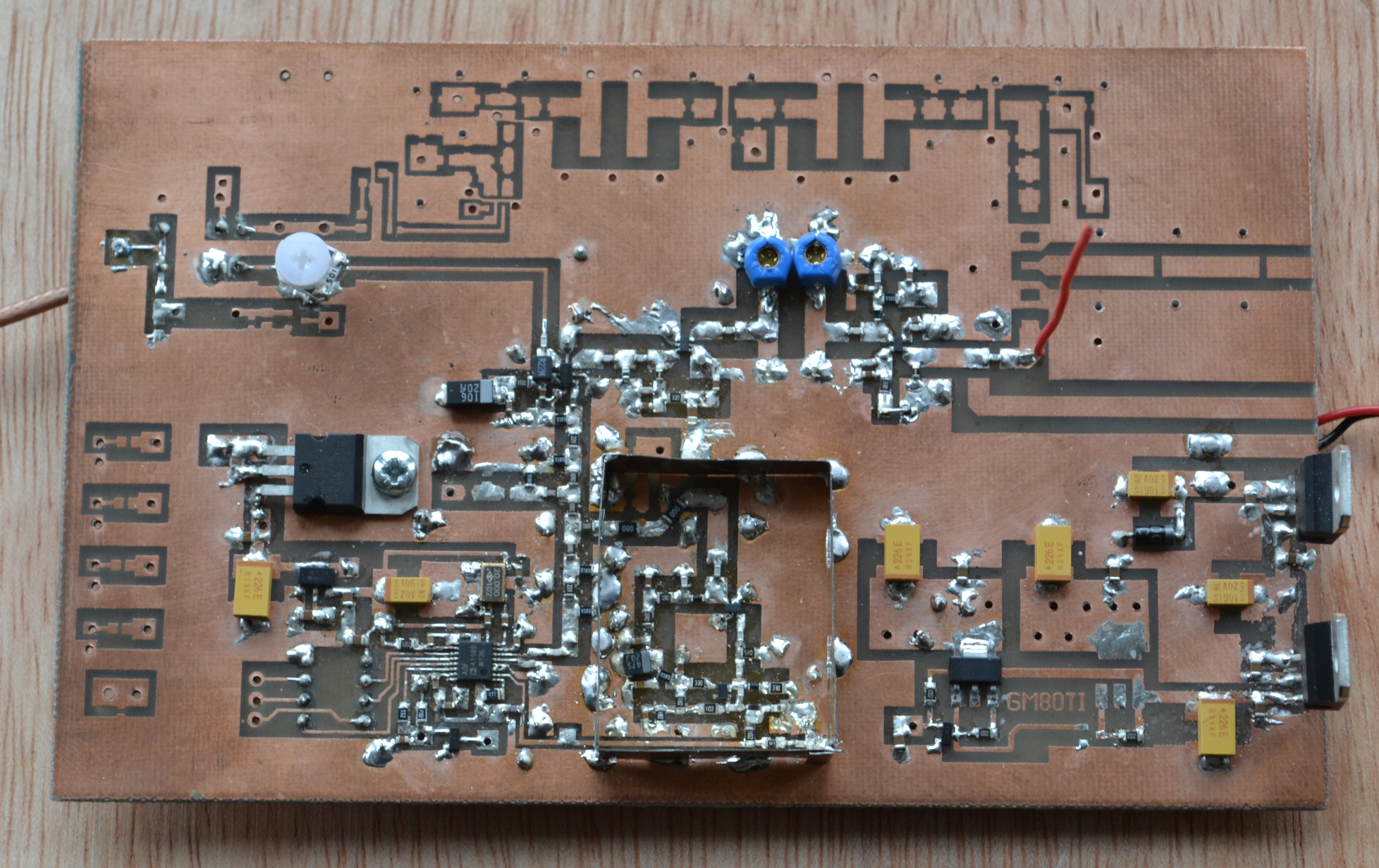
I found a few little errors on the board and in the design as I
built the prototype, but got the receive side working fine; I found
a screen over the VCO helped keep things stable. Problems started
once the transmit side progressed into the amplifier and filter
chain. I had very
few problems with this on the 13cm
transverter, even with similar simple bandpass filters, but
was not attempting to get the power up very much. Here I found that
I needed to add screening over the filters as I progressed up the
amplifier chain in order to keep things stable. However I was unable
to complete the chain and maintain good stability and enough power.
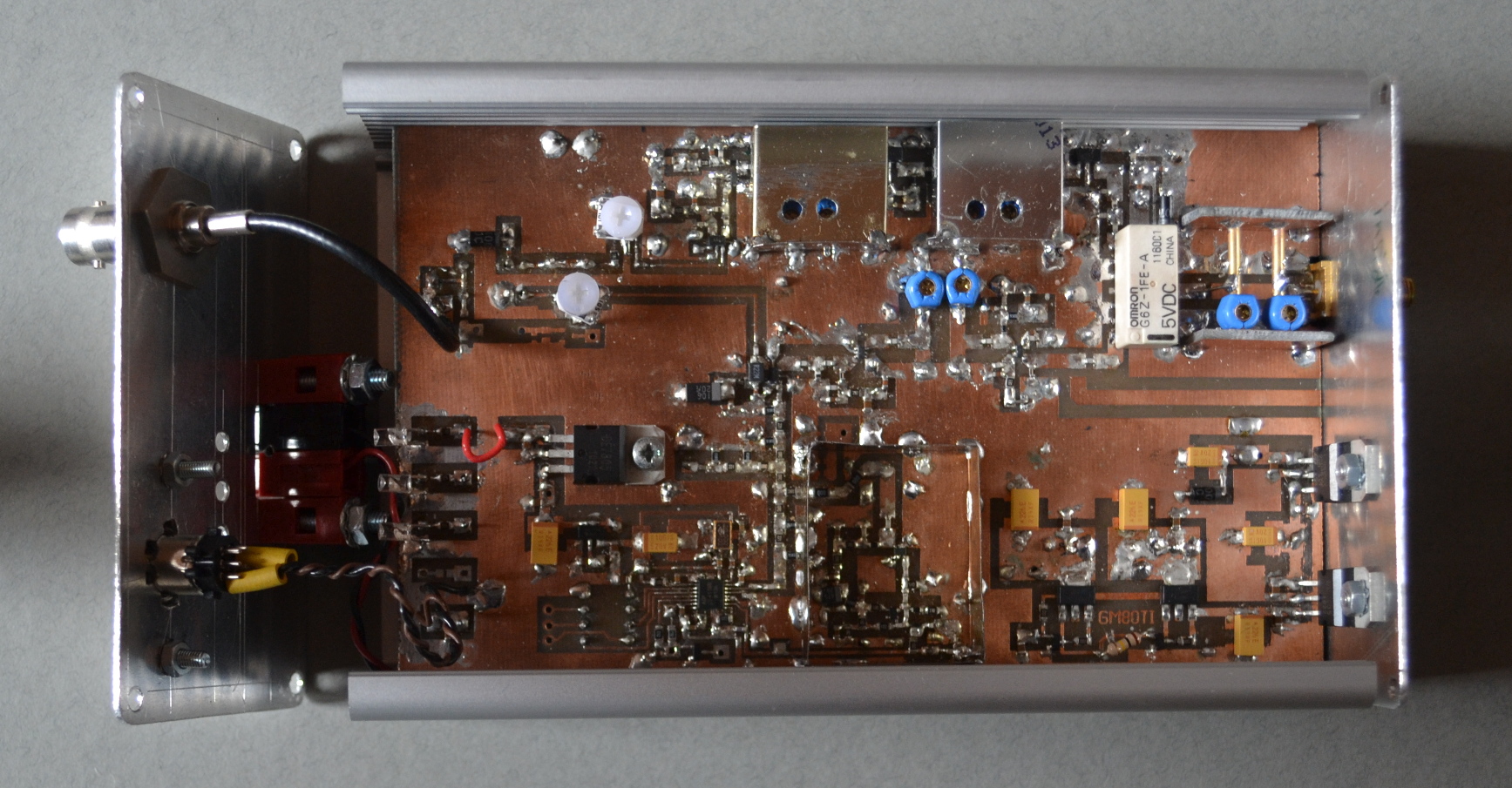
This was a bit disappointing! However it enabled me to integrate
everything into the box and get a good idea of what should be
possible with better screening. Here's the prototype (with removable
screening lids taken off):
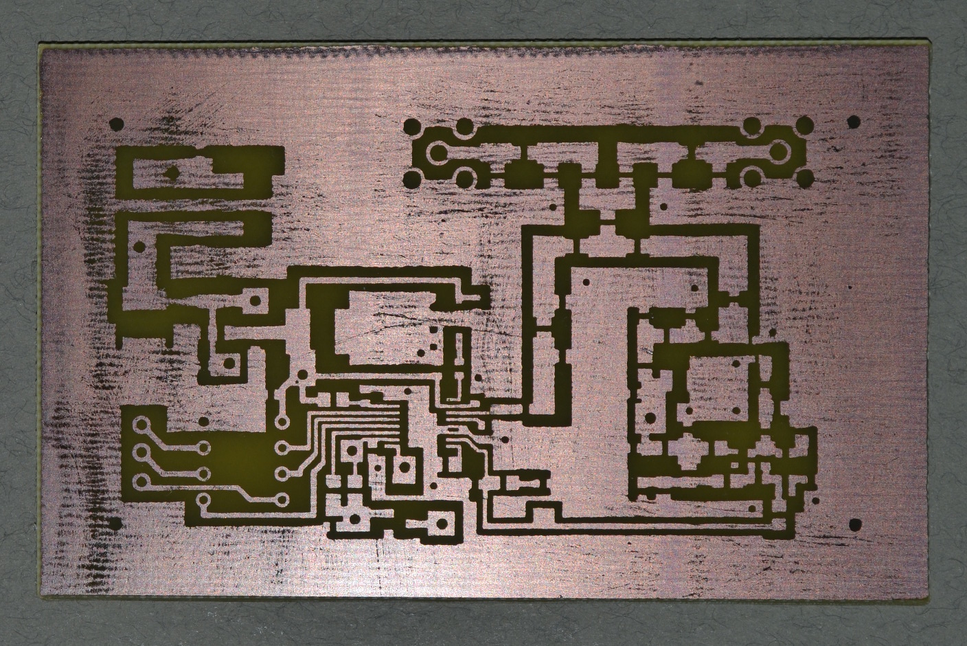
I decided that, rather than trying to fix the prototype, I would revert to a design with much better screening over the individual sections of the design - LO, receive side, transmit side, and a separate PA. I will build these sections as individual modules (though they could be incorporated on to a single board) to make build and test easier for me.
Here's the new LO module ready for construction (August 2014). Each
module will have its own voltage regulator, and will have coax
connections (can be SMA or SMB) for interconnects to the other modules.
I'm hoping I'll be able to keep things stable this way!
Next - trying out my new screening ideas.