
John's homebrew pages
An improved portable 23cm (1.3GHz) transverter, this time with 144MHz IF
There are several things I want to do to add to the first
transverter, but
these would add boxes and weight which is not ideal for my /P
operations for SOTA. So I want
to make use of some of the things I've
learned with the first transverter, and build another one which is much
more compact, simpler and lighter.
This time it will have a 144MHz IF. I realised there isn't really a
need to use 432MHz for 23cm, especially as I now have an old Trio 2m
multimode radio for potential talkback. I'm starting with a new and
much simpler local oscillator, then the transverter itself will be
somewhat simpler than the first. Hopefully I can get everything,
including the 5-10W PA I intend to build, into a single box. We shall
see!
Here's the board for the local oscillator, 37 by 74mm in size.
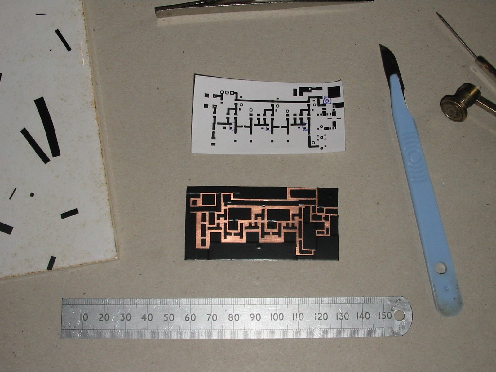
It will use a computer type crystal oscillator module at 64MHz, and SMD inductors in the tuned circuits (apart from a Toko helical filter at the LO frequency).
The board was assembled a stage at a time, as usual; the power
supply first, with 8V and 5V regulators, then the SMD oscillator block,
then the multipliers in sequence, checked out with wavemeters, RF
sniffer and RF probe at each step. I had to change the inductors for
the second multiplier as I hadn't allowed enough for stray capacitance
on the board. In the photo below, the SMD oscillator (64MHz) is top
left; the pink trimmer capacitors are for the 192MHz circuit, and the
blue for the 576MHz circuit, each with a BFR92 transistor. The third
BFR92 drives the Toko 2-stage helical filter mounted on the groundplane
side; the output from the filter goes into a MAR-3+ MMIC (middle right
on the board).
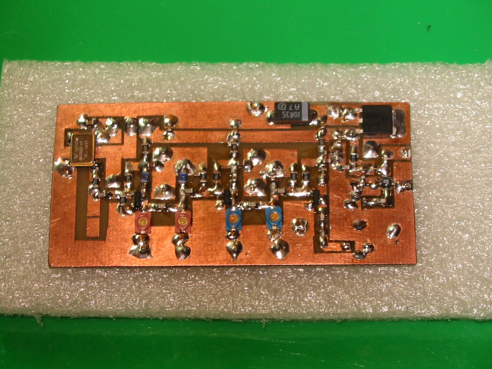
The spare copper lands (bottom left) were for a 64MHz fundamental filter, as in the W1GHZ designs, but it works fine without; I'll try that later.
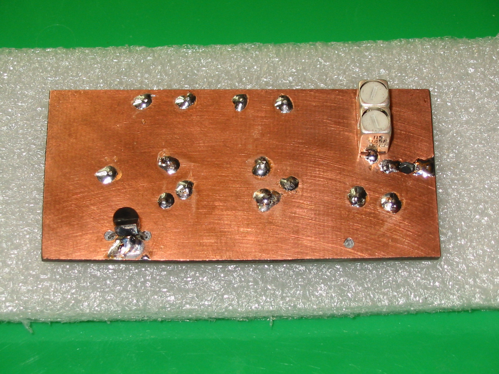
Here's the other side of the board. The 5V regulator is bottom left,
the Toko helical filter top right. The filter needed about a turn or so
in to get it on frequency, and adjustment is fairly flat. I checked the
frequency using the 7th harmonic of the crystal oscillator (in the 70cm
band), and at 1152MHz it's about 5kHz high. That's great, easy to
correct for when tuning. It's about 10 times better than the spec of
the oscillator!
Even without the MAR-3+ I had nearly 1dBm of output; with the MAR-3+
in circuit I get a good output at about the full 10dBm it can produce,
which will be fine to drive the mixer after an attenuator. It produces
a lovely absorption dip as measured on the RF sniffer connected to the
coupling loop on the wavemeter as I go through 1152MHz.
Circuit to follow once I've re-drawn it - quite a few component
values got changed from my original idea.
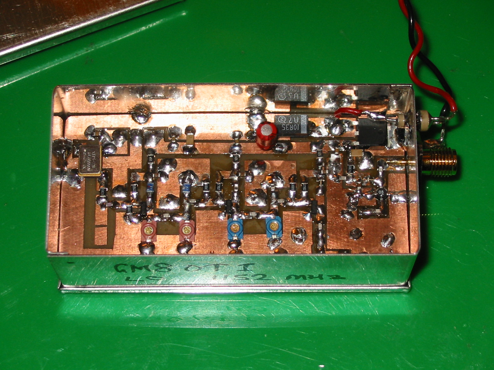
Once installed in the tinplate box I found I needed to add more supply decoupling to get rid of a 60kHz approx oscillation, but a nice 10µF capacitor soon fixed that, and it still produced the 1152MHz as required. That completes the local oscillator.
The next step was to design the main board layout, then mask it up
with vinyl tape and etch it as usual. Once done, a start was made on
the IF switching, followed by testing the drive levels for the mixer
from IF rig and LO. The Tx from the IF rig (FT-817) is at about 0.5W
which needs to be sunk - hence the ten 510 ohm resistors at the bottom
of the board in the photo below which make a suitable 50 ohm load.
There's then an adjustable attenuator to get the level right for the
mixer. The LO output was also a bit big, so I added a little pi
attenuator - I'd left space on the board for that, and for an
additional amplifier if needed which fortunately it isn't.
Once that was done I thought I'd add the mixer (a Minicircuits
ADE-5) as the last job for the day - and for a bit of fun I added a 6cm
bit of wire as an antenna on the RF port of the mixer. I was more than
surprised that with this I could detect fairly easily the local beacon,
GB3EDN - even without any RF amplification! The photo is a bit fuzzy, I
was very excited by this ...
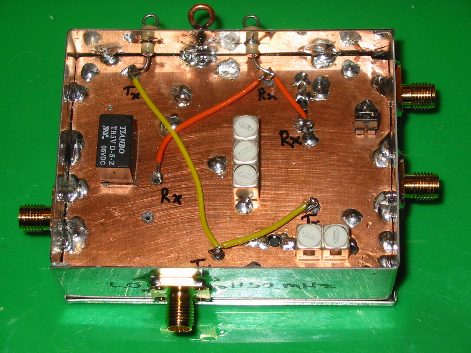
The next step was to get the 23cm helical filter and the Rx
amplifiers added, then do the Tx side. With these added it was time for
testing. The receive side was still OK, but the transmit side had
little output. I thought I had calculated all the gains and losses
properly, but clearly the losses were winning! So a bit more gain was
added by replacing a MAR-3+ with a MAR-6+ to drive the output GALI-5+,
and we seemed to have a working system with about 16-17mW of output. A
bit lower than I'd hoped, but probably enough to drive the planned PA.
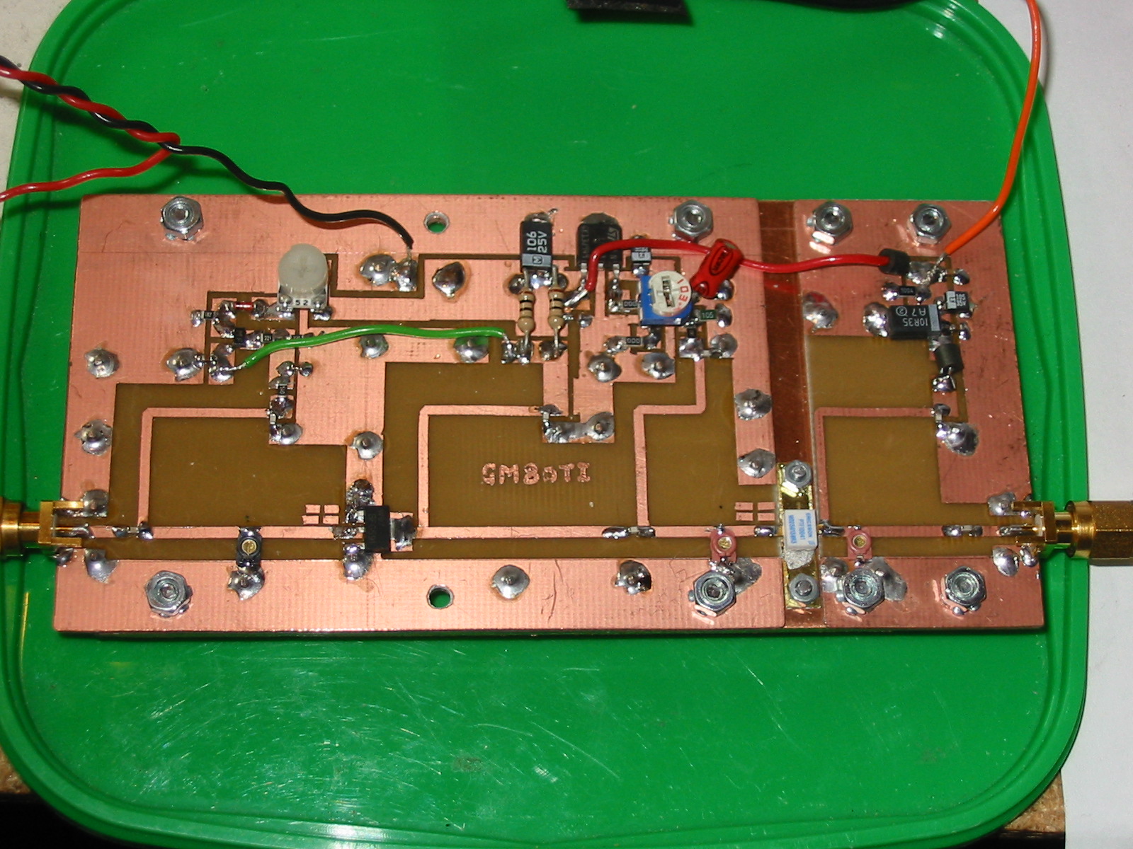
Here's the component side of the board; the ADE-5 mixer is clearly
seen in the middle. The resistors on the left are the IF load (I need
to sink up to half a watt from the FT-817). If you click on the image
to look at the full size version (all the images in my amateur radio
pages do that, by the way) you can see the MMICs in the receive and
transmit chains, which are joined by a resistive splitter before the
3-stage 23cm helical filter. The transmit stage has an additional
2-stage filter between the MMICs.

The other side of the board - the groundplane - has the IF switching
relay (left), the Toko filters, and the power wiring.
With a working transverter I was able to do a test on the local
oscilator. Since it is based simply on a tiny fixed frequency crystal
oscillator module, I wondered how stable it would be, and how close to
the specified frequency - I had an initial look at this as noted above.
I set up to receive GB3EDN, and with a switch-on from cold, noted the
frequency needed on the FT-817 to zero beat with the beacon. The
results are plotted below (click on the graph to get the bigger
version).
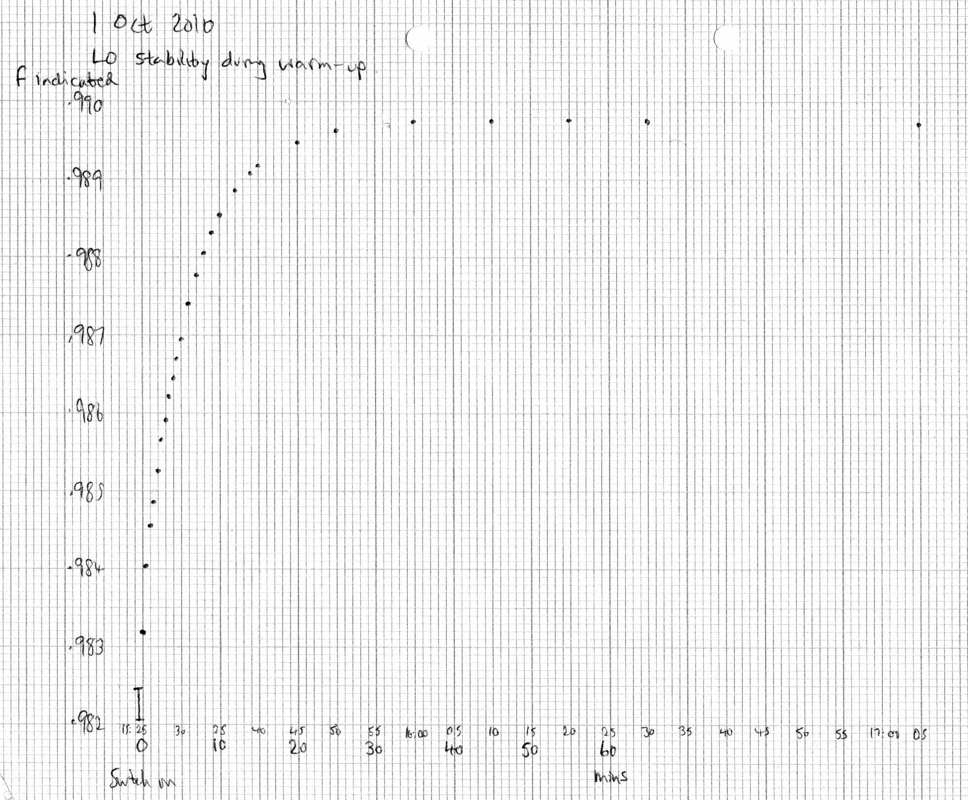
You can see that the frequency shifts quite rapidly over the first
5-10 minutes, from about 8 kHz low (i.e. the LO is 8 kHz high) and as
it warms the LO comes down in frequency, making the beacon appear to
drift to a higher frequency. It is within 1kHz of the final frequency
after about 10 minutes, and within 100Hz after about 20 minutes - at 30
minutes it's effectively stable. It's interesting to see that it
settles to show the beacon at 1296.9898 -around 200Hz from the
specified beacon frequency of 1296.990 (assuming the beacon is actually
on frequency!). Over the next hour the LO frequency was very stable.
Hopefully it will behave similarly in the final box - it's quite well
insulated from the outside environment and runs pretty warm, so should
be similar.
So with the transverter working, it was time to start on the PA stage. First I designed a version combining the BFG591 driver I'd used in the first transverter with the PTF10041 FET I'd obtained from RF Elettronica. Again I used Puff to put the design together. It looked as though it might be OK, though the bandwidth was pretty broad. I decided to mount the whole thing on a copper plate, so that I could heatsink the output FET properly, if it happened to manage as much as the hoped for 5-10W! Here it is, with the FET mounted on a brass strip (easier to solder to a small plate) for the grounded source connection. The circuit board is in two parts, with the BFG591 on the FET gate side.
Sadly this was not a success. It was not stable as I had hoped, and
the FET side went into oscillation rather easily as I tried to tune it
up. In the course of making measurements and adjustments, I was
continually chopping and changing and at one stage had accidentally
left off the dummy load. I suspect this was the cause of the FET's
death - the oscillation it was producing, reflected back into the
device, may have killed it. It certainly wasn't static, I'm always very
careful about that. However, the first device now has an interesting
1.5 kilohm resistance between the gate and source. Fortunately I had
bought three of them so there was still a chance of success!
So - back to the drawing board. The RF Elettronica site had a
suggested design for the FET amplifier, which I'd put into Puff and not
been terribly happy with, in that it didn't seem to match well using
the only S parameters I could get hold of for the device (unfortunately
not for the conditions I wanted to operate it under). However, looking
again at this it seemed that with a few tweaks it might be OK, so I
built a board for the FET alone based on that design. Here it is under
test (click on the photo to see more detail of the board). Again it's
mounted on a copper plate for heat sinking purposes; it will be
attached to the final box using another copper plate.
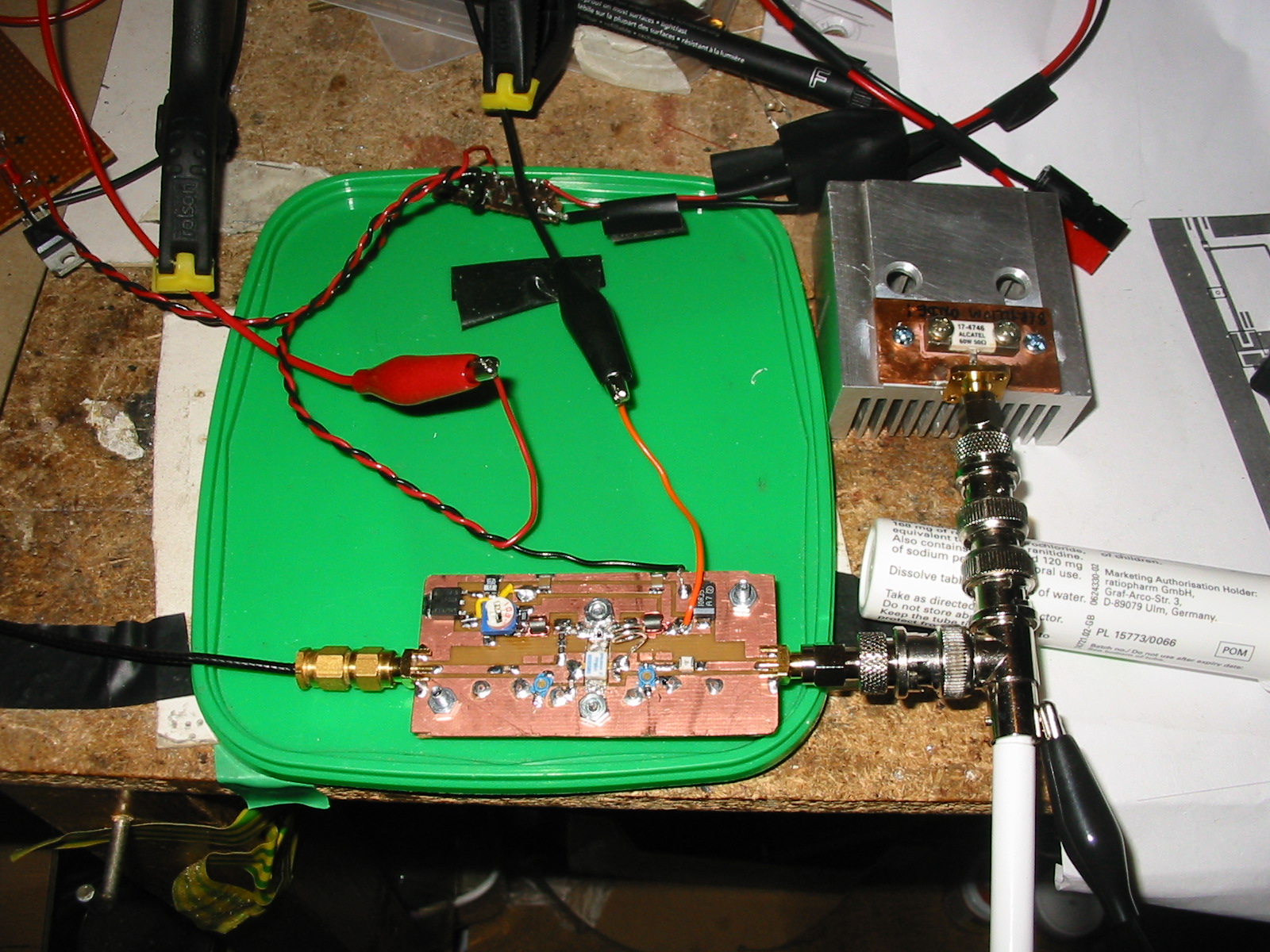
This proved rather more successful, though I had to make a few
tweaks to the design on the website to get it working - I'll draw out
the circuit in due course. Using my little RF probe, the indications
were that I was getting somehting like 13dB of gain out of it, which
looked very hopeful. So, time to look at the driver stage again.
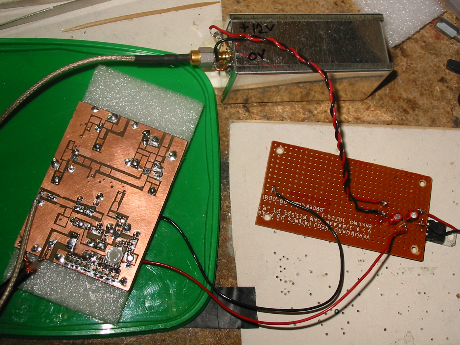
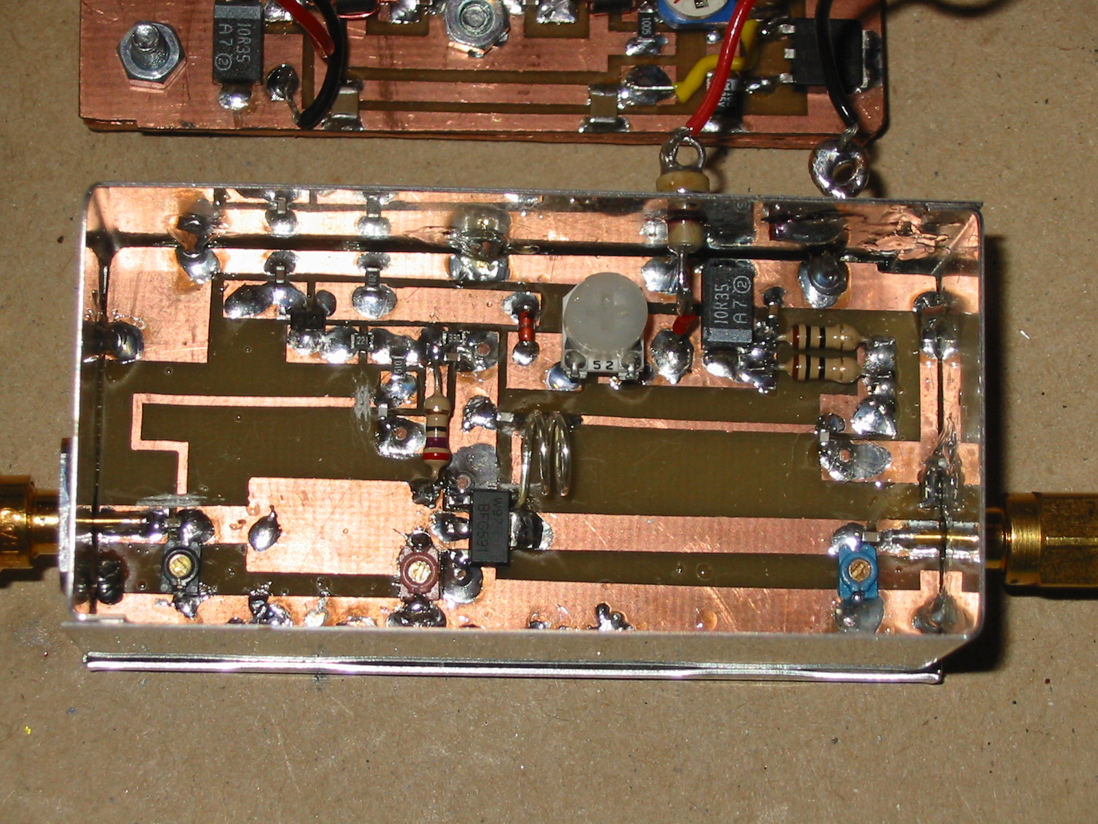
I was determined to et the BFG591 working if possible, and
re-designed (Puff again) the board to be a bit shorter so it would fit
in a standard size tinplate box. This might have been a mistake, in
that I didn't seem to be able to get it to operate in a really stable
manner; at one stage, it seemed to oscillate at a frequency some way
below 1296MHz when driven. No fiddling around with the matching seemed
to help. Eventually I decided on a more drastic measure - to isolate
the quarter wave chokes I'd used on the base and collector supply
lines, and instead use a small inductor on the collector, and a
directly wired "ordinary" (not surface mount) resistor to provide the
base bias; these can be seen in the photo below. I had some concerns
about the consistency of measurements made with my hand-held RF probe
(even when plugged directly into a BNC socket as in the photo above) so
built a new RF detector inside a BNC plug - see the aside descibing
this and a directional coupler.
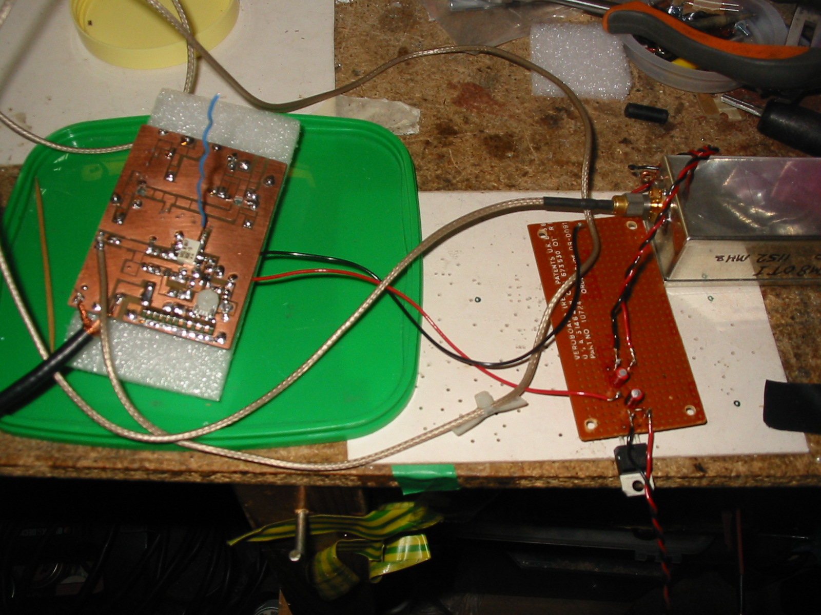
The change to the bias supply and collector DC feed seemed to make
things more stable, and so I added the FET PA stage after the driver.
Using the new RF detctor, it seemed to be working OK even though I
think
it can be tuned a bit better - at present the RF detector suggests it's
only producing about 1.5W, though it might be more (or less!).
This was encouraging, and I thought that before I did more tweaking
I
needed to try some on-air tests, since I was not totally convinced that
the
signal was as clean as it ought to be, and I couldn't tell one way or
another with only the RF detectors to make measurements. The output
goes up and down with speech using SSB, but only on-air tests will make
sure it's actually OK.
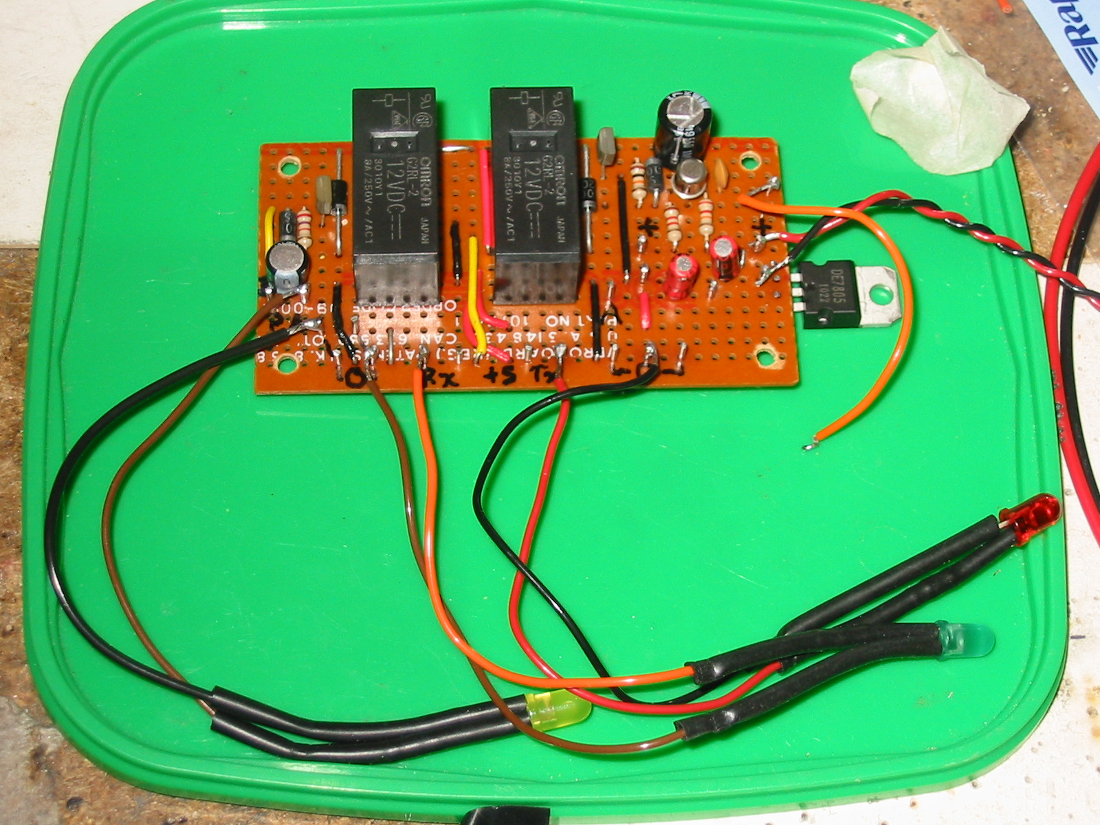
Here's
the power control (sequencer) board, arranged with delays on the power
lines so that the PA is switched on last and off first. The LEDs light
in the right sequence to show it's all working. The antenna relay board
was also on the list of bits and pieces left - it's in the top right of
the photo below.
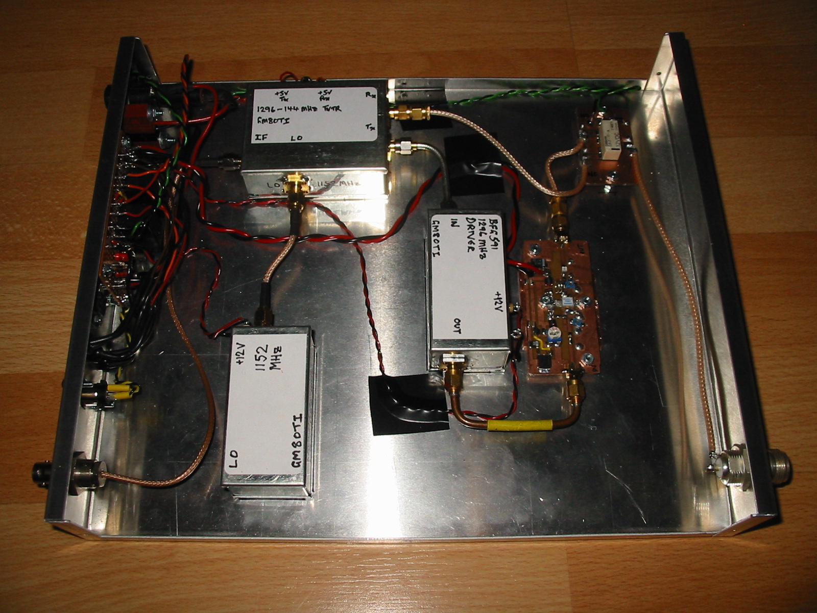
Here's everything laid out and fastened down in the box. (Click on
the photo to see it in more detail.) Note that the PA is the only RF
module not in its own screening box. It's a bit bigger than I'd
intended, but Maplin didn't have a slightly smaller version of this
nice 5cm high box in stock when I went to the shop. Plenty room for
future developments though - this will be my 23cm transverter box for
all future /P use.
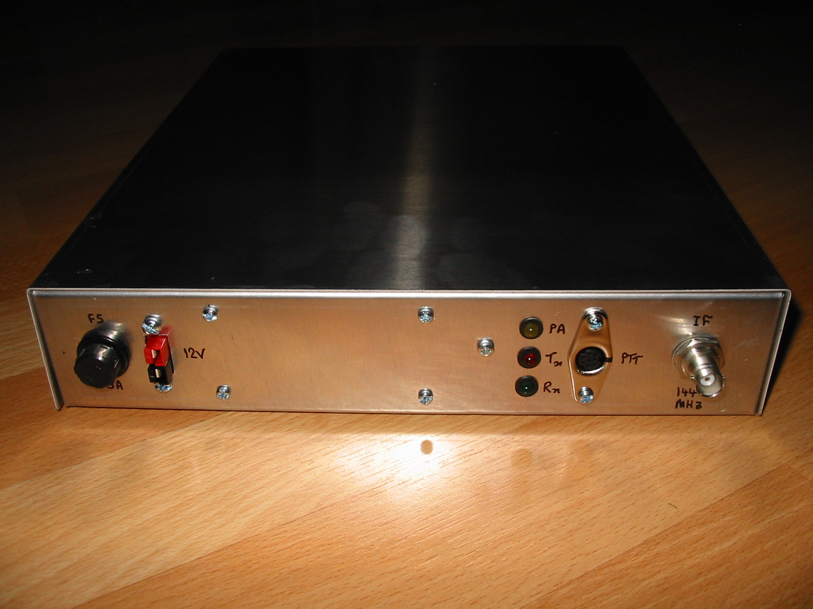
Finally here's the front panel, and the lid put on (and it still
works with the lid on!). The LEDs for the sequencer are nicely laid out
to show it's all working. Power is through the usual Anderson Powerpole
connector, and the IF goes through the BNC connector on the right.
There's an N connector on the back of the box for the antenna.
Tests once it was in the box were very promising. I used my new directional coupler
to measure power, first on the original (Mk I) 432MHz IF transverter. I
added a resistor in series with the meter on the coupler so that the Mk
I gave a reading of about a fifth full scale, so that it would cope
with about 25 times as much power from the Mk II 144MHz transverter.
When I pressed PTT on the new transverter though, the meter needle hit
the end of the scale quite hard, so the new transverter puts out quite
a lot more power - indeed, my 400mW estimate for the Mk I transverter
may have been rather optimistic. I changed the series resistor in the
coupler to give a better (about half scale) reading with a carrier
input. When using SSB input, the needle went up and down nicely with
voice, so I thought we might be there - hopefully there would be no
nasty
surprises in an on-air test. DC measurements also suggested that at
present (before final tuning) I am getting around 2.5W out, which is
within the right ballpark.
Having arranged a sked with Jon GM4JTJ I set out to Hillend in hope
that all
would be well. I heard Jon come through on time, at the point on the
dial I roughly expected (knowing the frequency drift and offset as it
warms up), and was very pleased to be told that the signal level was
significantly up on the previous transverter. Here's the setup - as
noted before, the box is a bit big (though allows for developments),
but it's a much more convenient setup than I had before, since
everything (apart from the battery and antenna!) is in the one box. I
will probably tweak it a bit to see if we can get a little more power
out of it, but it's now very satisfactory anyway.

So another success on 23cm - now to start thinking seriously about
the move up to 13cm.