
John's homebrew pages
2m diameter portable dish antenna
I had seen a great design for a dish antenna with stressed struts to form the surface in the International Microwave Handbook (2nd edition, 2008). However it was very well engineered in metal, and I don't have the facilities to do that. So I decided to see what I could do using easily available materials from the local DIY store.This portable dish was written up and published in Practical Wireless, October 2011. You may be able to get a copy of the article which has full details from Practical Wireless.
I did some calculations on stressed rods, and decided that this
technique would give a shape close enough to parabolic for the
wavelengths I was interested in - 23cm and 13cm. Provided the surface
is accurate to about a tenth of a wavelength it should work pretty
well. Here's an outline of my dish as calculated, with the feed shown
at the focal position, and the strings used to stress the rods shown
dotted:

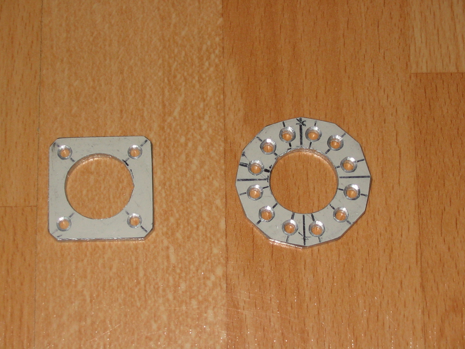
The strings are supported at the ends in aluminium rings which I
drilled and filed to shape. There are 12 strings (one for each radial
stressed strut) on the front side, and four on the back to hold the
structure back against possible collapse!
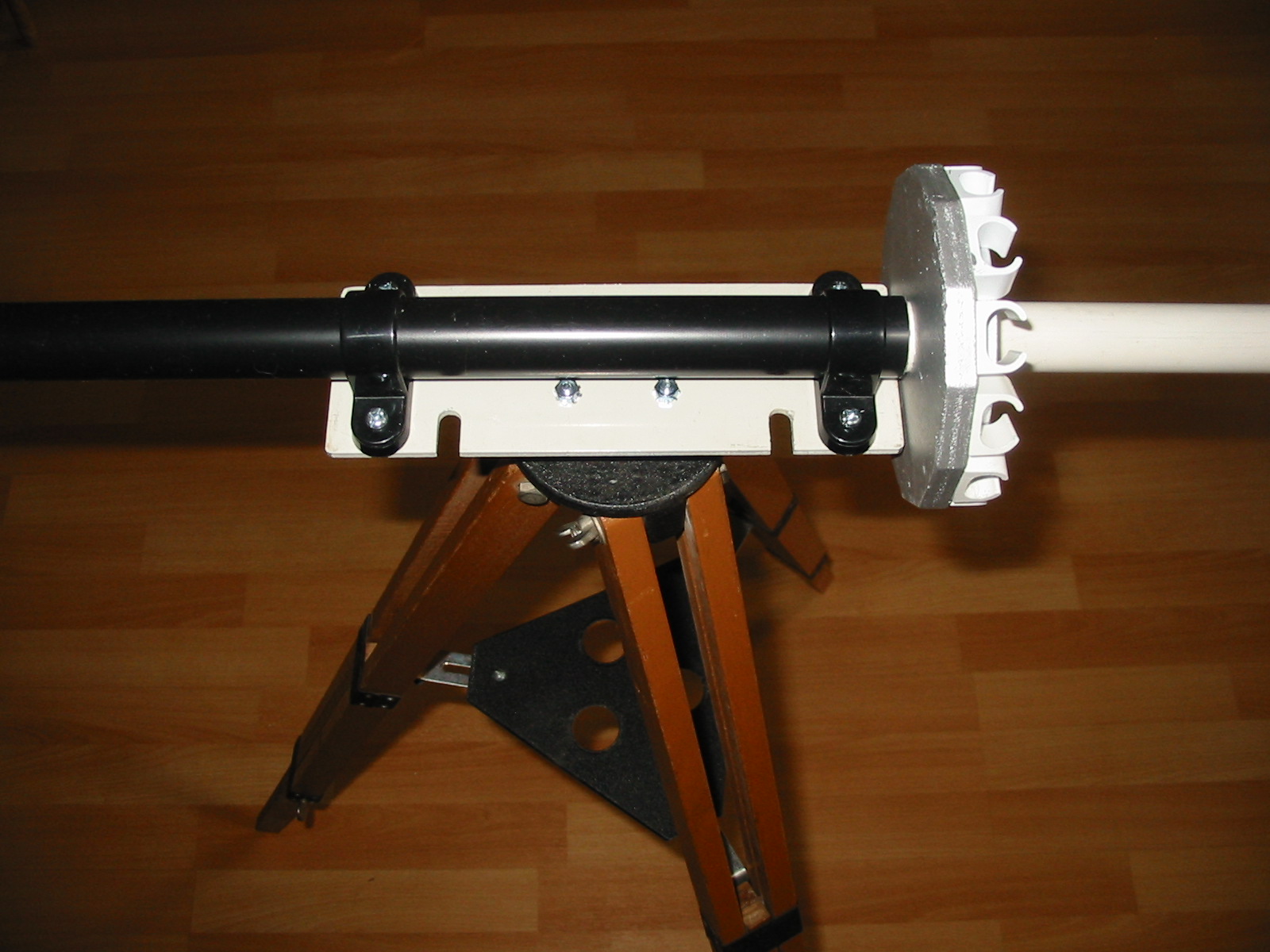
Here's a close-up of the completed centre support section. The tubes
are 25mm electrical conduit and 23mm water pipe which slide nicely one
in the other. Standard clamps hold the tube on to a flat plate which is
supported on a tripod. The centre hub support for the stressed struts
is made from plywood (painted silver!). The stressed struts are cut
from oval plastic electrical conduit, which is very light in weight but
seems strong enough and bends nicely. The ends are held at the hub
using the appropriate conduit clips, which are screwed to the hub.
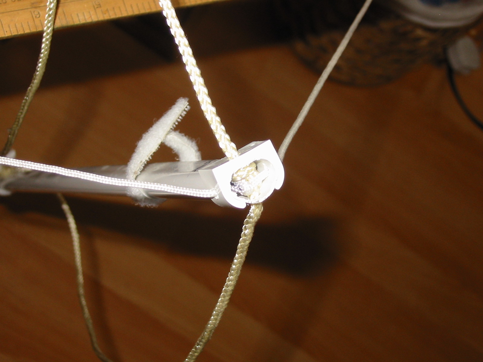
At the end of each strut I use another conduit clip, and drill holes to
take the radial strings (held in place by a big knot inside the
conduit). There are also holes so that a string can be taken round the
circumference of a dish, to hold the struts in place whilst the mesh
panels are fastened on. The mesh panels are held in place by Velcro
tape - using hook and loop you can make little loops that can be
unfastened to fix the mesh panel in place.
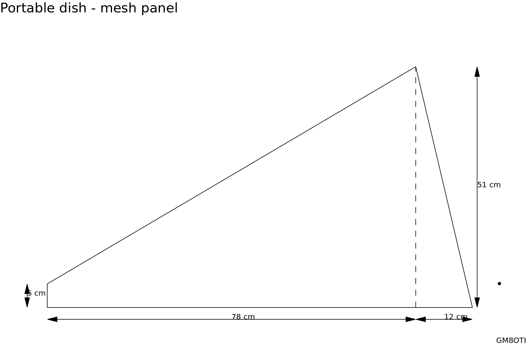
Here's the outline of one of the 12 mesh panels. I used 13mm square
mesh which will work fine at 2.3GHz since the holes are only a tenth of
a wavelength in size. It bends to the shape of the dish easily.
I had already tried a bi-quad antenna
(see "23cm quad loop") for 1.3GHz, and decided that this would give a
good radiation pattern to illuminate the dish well. Here's the design:

The balun is made from semi-rigid coax, and forms a fairly rigid
structure; I used tape to hold it together whilst soldering the closed
arm on:

The radiating element is made from brass tube or rod:
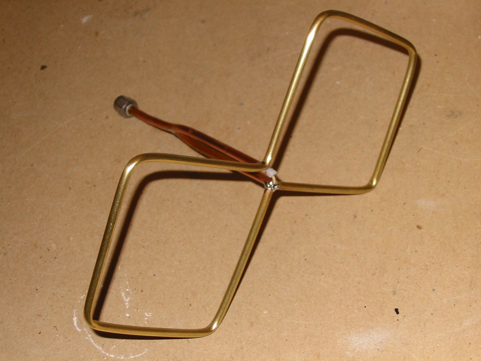
This is held in place at the end of a plastic tube using a tube
connector with slots cut to take the radiating element. The end piece
of tube supports a flat mesh panel to act as a reflector; I adjusted
the distance to this using a power meter to get the best match.

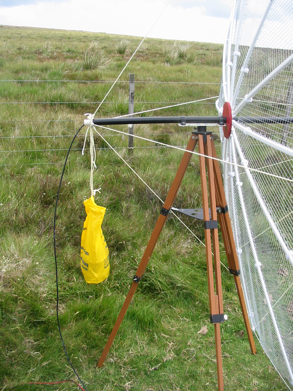
This photo shows the arrangement set up. The hub is now painted red!
You can see the tensioning strings at the front, the four support
strings at the back (it's quite flexible so a strong wind can distort
the dish - probably 12 strings at the back would be better), and the
mesh panels held on by Velcro clips.

The dish doesn't weigh nothing so does need a bit of a counterweight to
make it balance on the tripod. I used a plastic bag with old billiard
balls in it! The feed cable runs up the centre support tube.
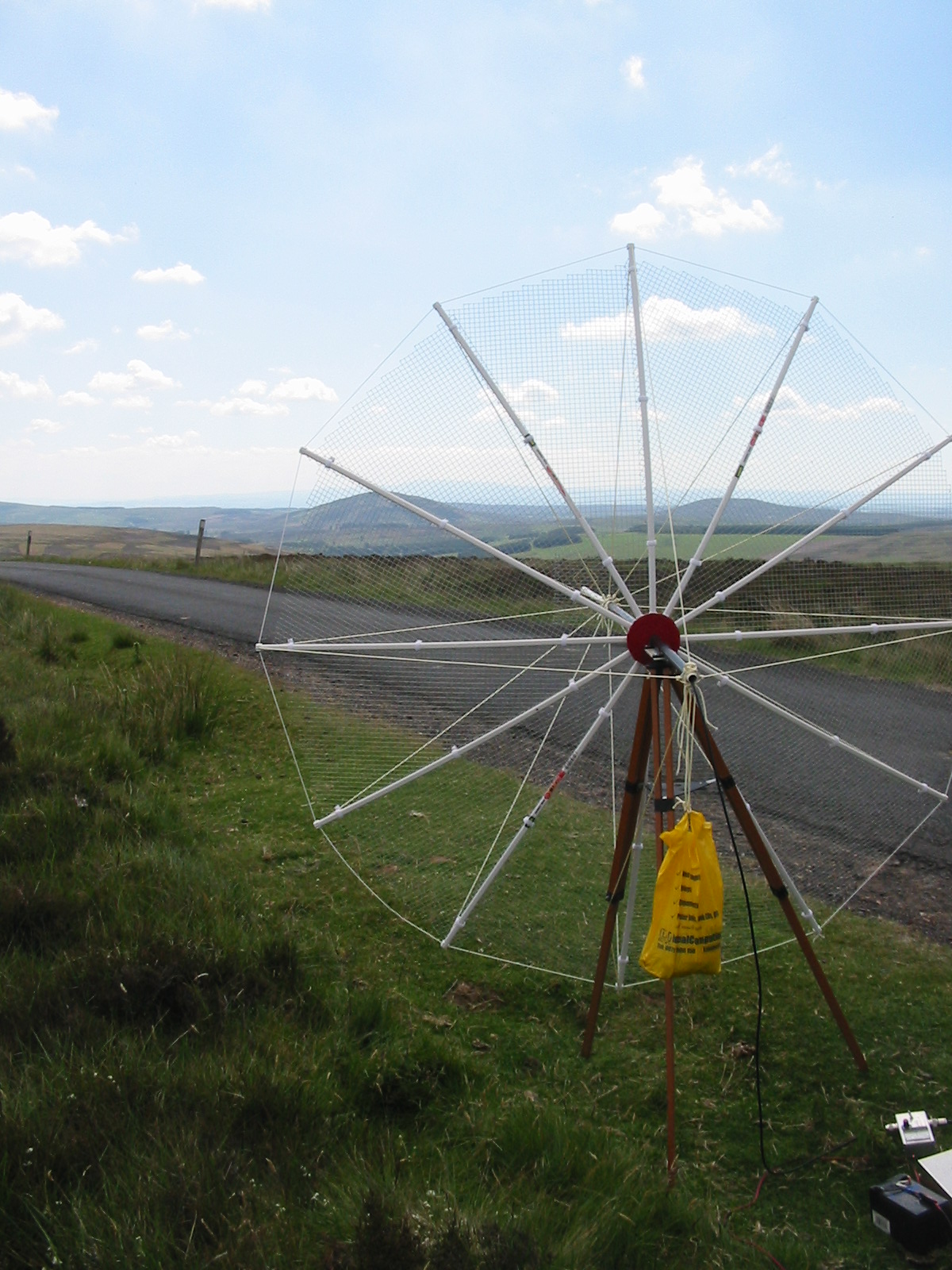
Here's the dish in use:

That day the view south over the Cheviot hills was very nice. I
had an easy contact with Lincolnshire with just a couple of watts of
power at 23cm.
This antenna hasn't been used much - it takes half an hour to set
up, so it's a bit fiddly - but it works well.