
John's homebrew page
Portable 2m linear amplifier
With the HF portable linear amp working nicely, it's time to add to the armoury for the FT-817, to make it a bit easier for those a long way away from the Scottish SOTA summits! Again, this one started as a result of Eamon Skelton's "Homebrew" column in the August 2008 RSGB RadCom, where Eamon had built a nice little 2m linear using quite a simple circuit, which provides great encouragement.
Heat sink
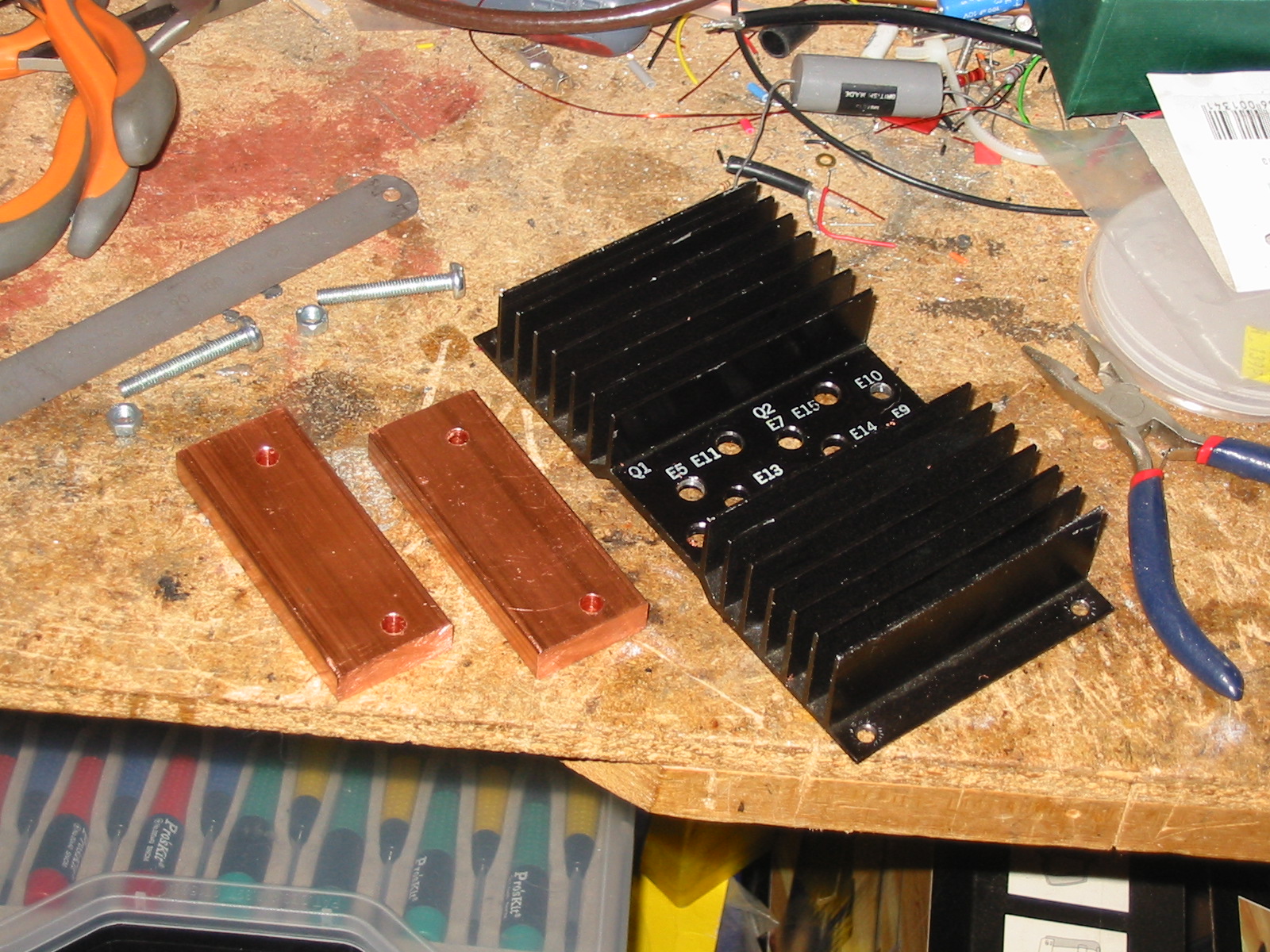
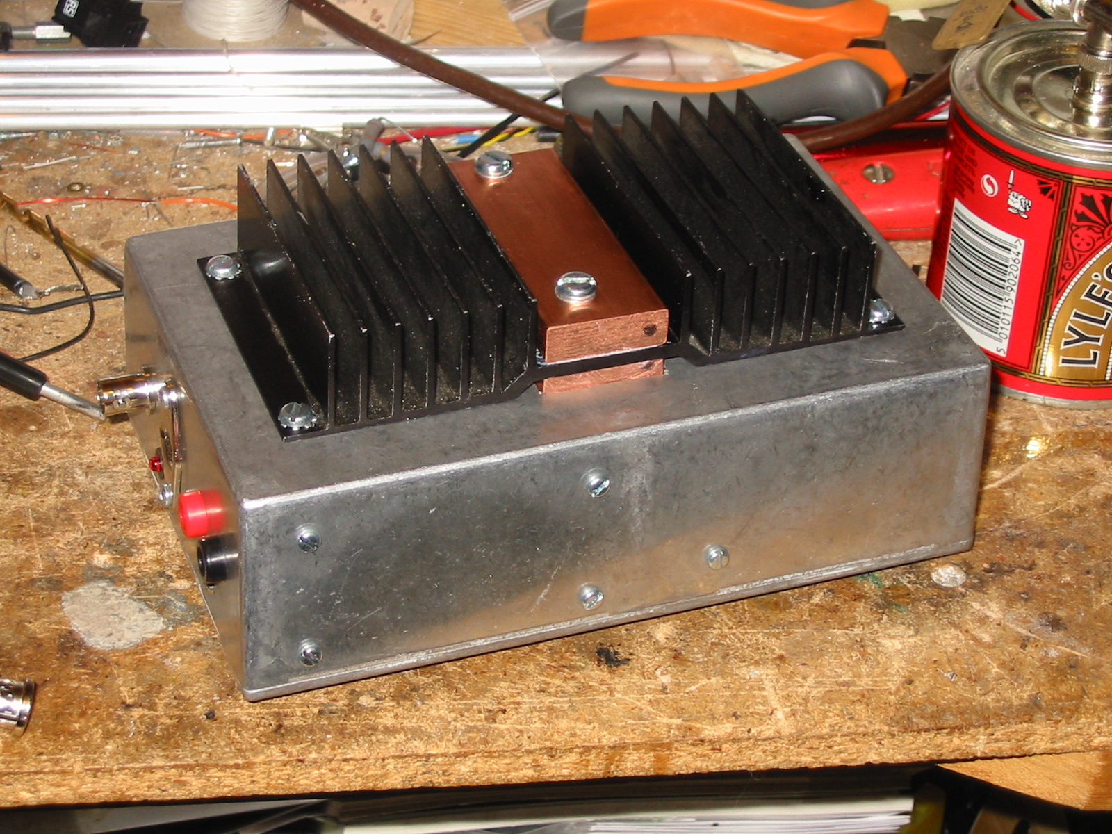
This is another using an old heatsink out of the junk box, from an old power supply - you can see the mounting holes for two TO-3 transistors. It's a similar construction to the HF linear heatsink, using some nice copper bar (10mm × 30mm) to extract the heat from the FET and get it into the heatsink. Again this is from Blake's metal centre and I have enough to make some interesting amplifiers in the future!
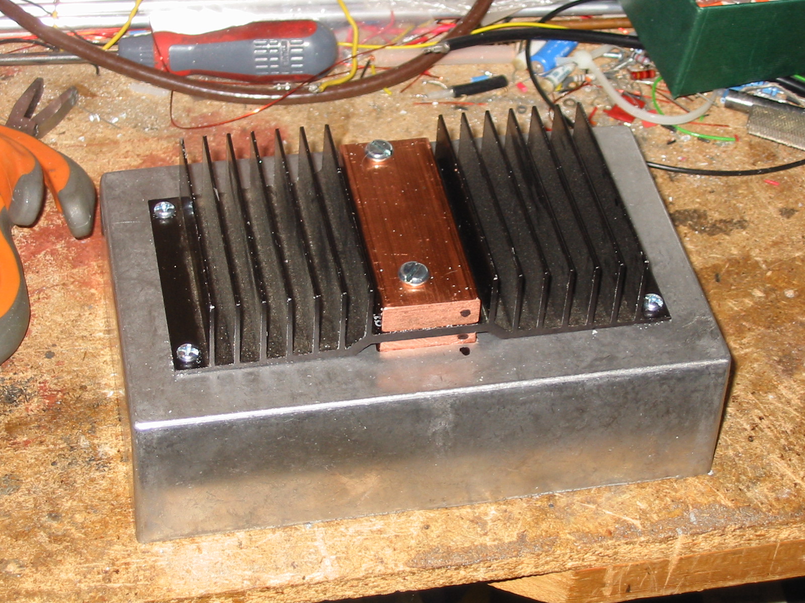
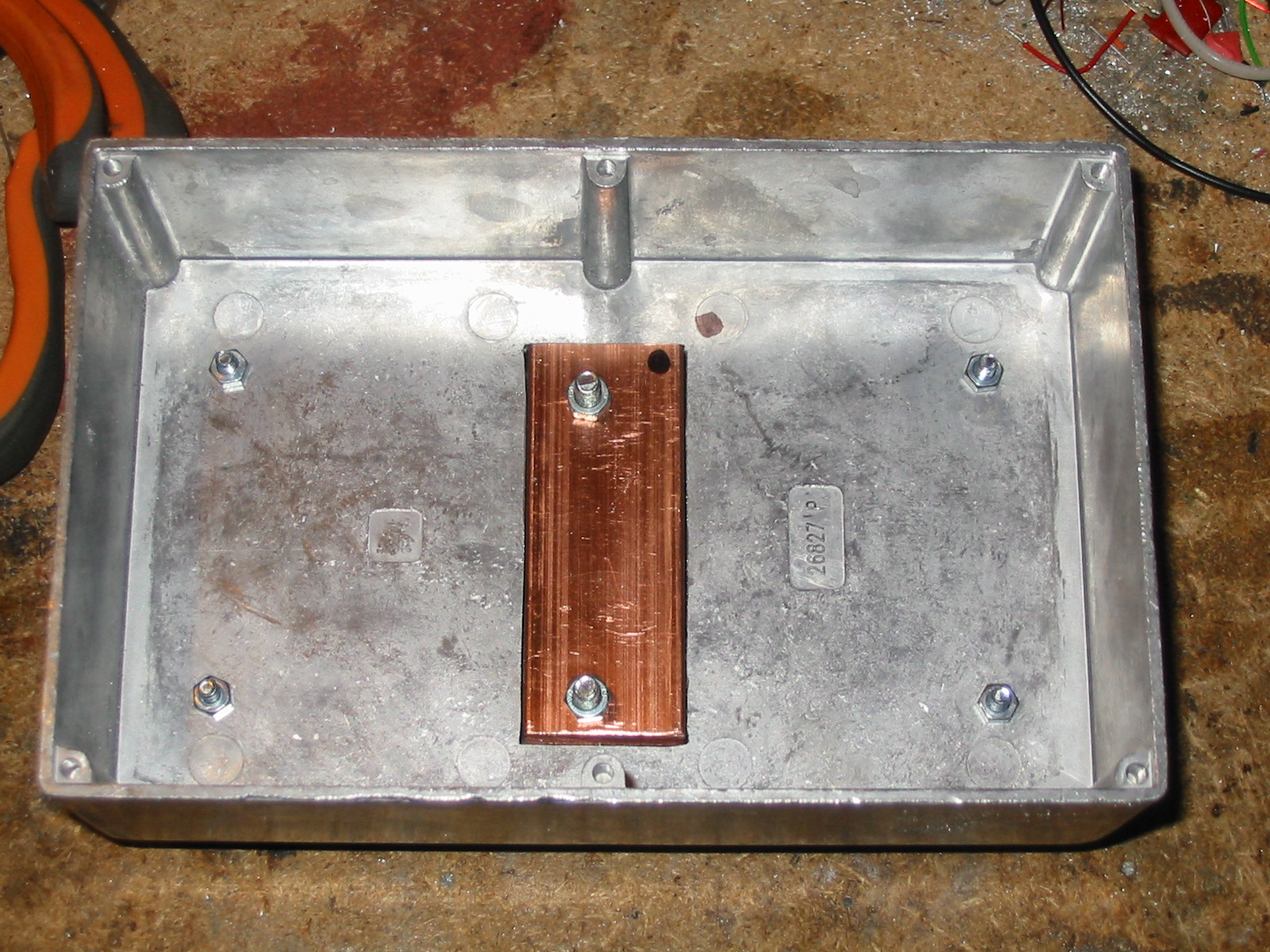
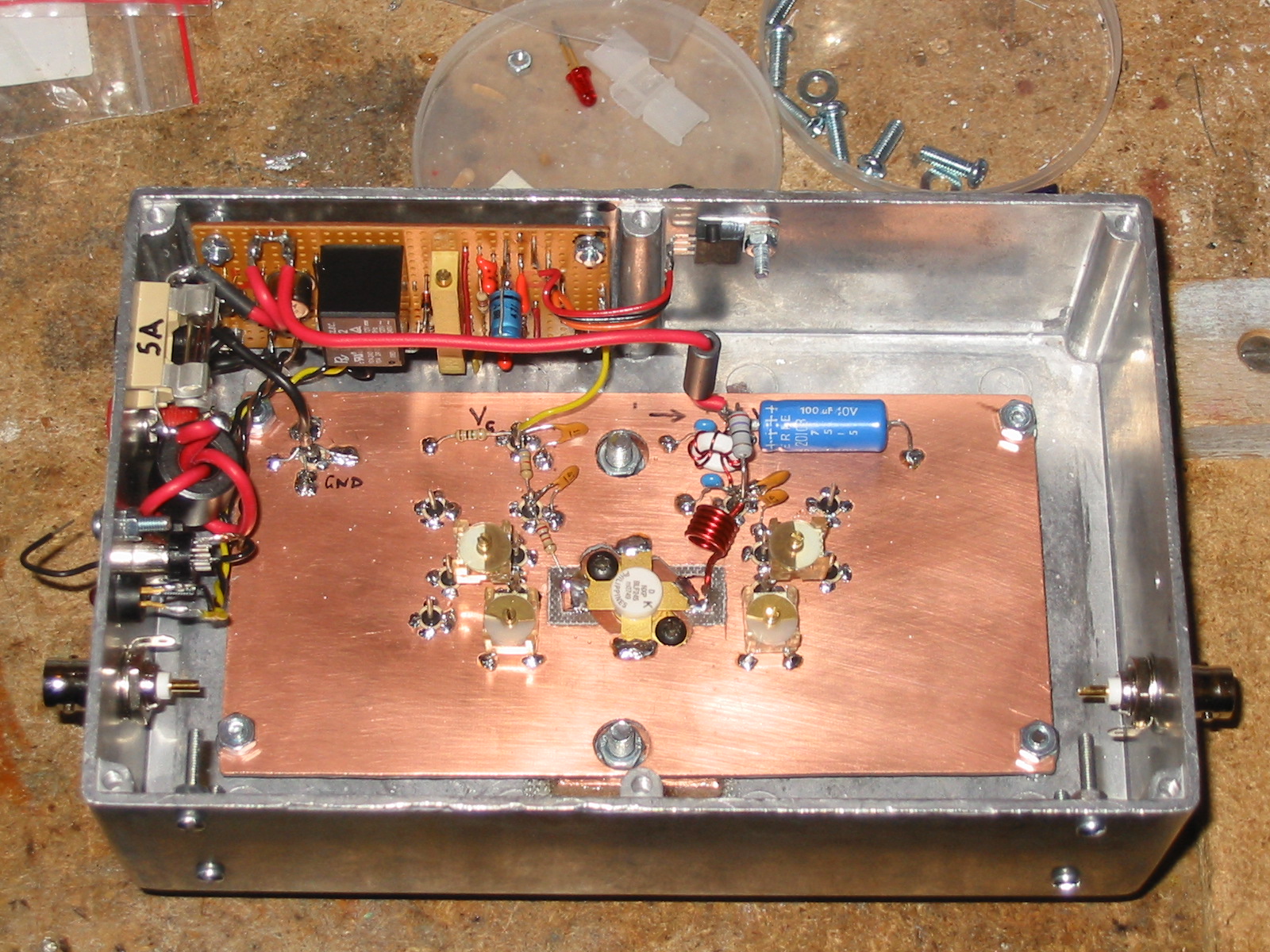
Below you can see this assembled into the diecast box; there's a hole cut in the box to get the copper bar inside for attaching the FET. This time I bought a proper VHF FET at vast cost so will have to be careful not to let any of Eamon's "magic smoke" out of it - that's one reason I started with the HF linear and cheap FETs.
Here's the copper bar brought through the slot in the box, waiting for holes to be drilled and tapped to take the FET. I investigated the price of taps and though I found one cheap enough, the carriage cost was horrendous, so since I do this so little I will be making another tap out of a steel screw. As with the HF linear, the screws fixing the heatsink to the box will also be used as standoffs to mount the copper clad circuit board for the PA section. The bias board, LPF, relay board, and probably preamp, will be mounted on the box sides.
Construction - first steps
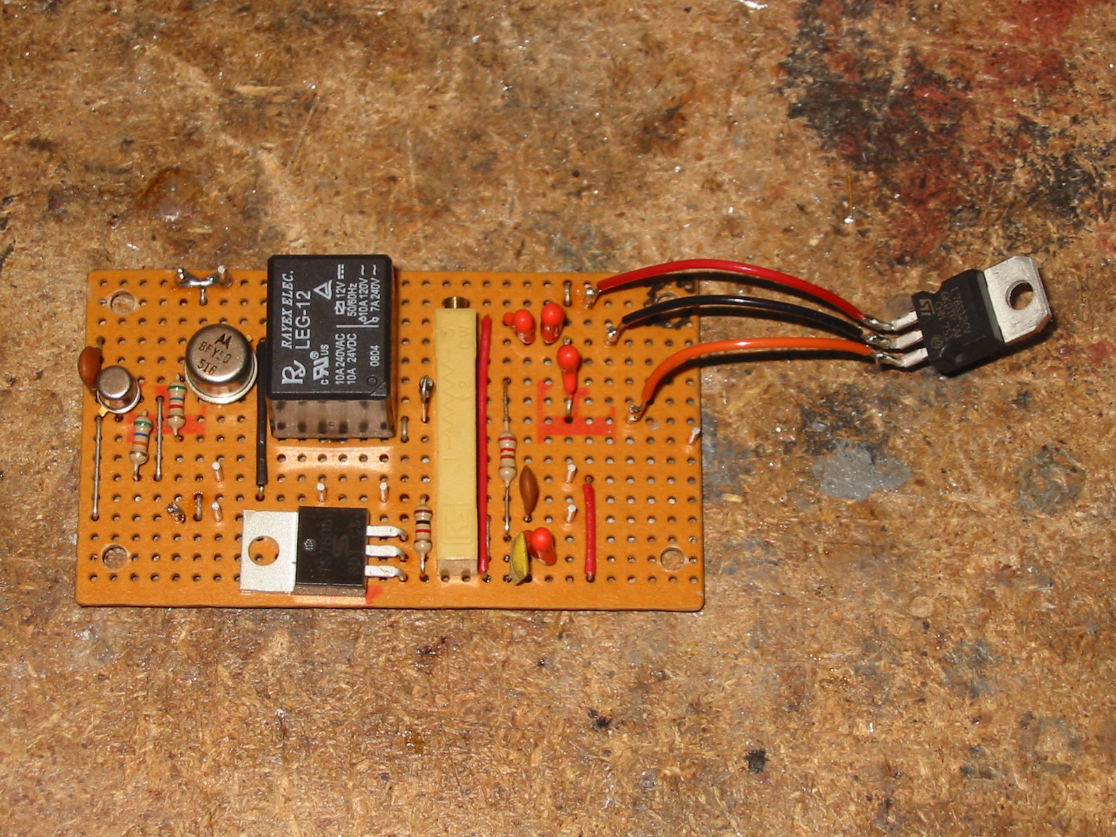
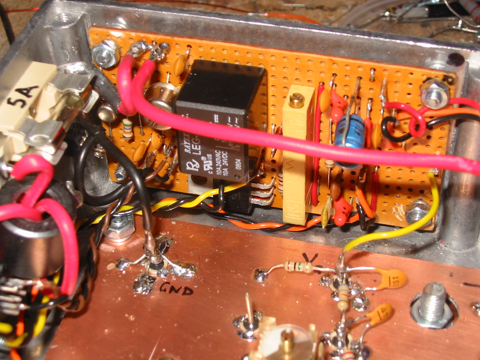
The bias and TX relay board is a bit of stripboard with the layout decided on the fly, mounting the biggest components first. The 7812 is on flying leads on the right so that it can be bolted to the box sides; it has to sink anything from 25V portable, and potentially up to its 35V limit if I build a nice mains supply. The 7805 is mounted on the board as it just provides the bias voltage; could have used a lower rated device but didn't have one handy. The trim pot for adjusting the bias is a lot easier to access for adjustment in this linear, by design!
Below, the bias board and PA board are now in place, with the PA board populated. Instead of real dead bug style construction, I used some glass feedthroughs cut off under the board as mounting pins for the components; allows dead bug layout but with more rigidity (there are a couple of spares for tweaking things). The board height was adjusted using washers on the mounting screws in the corners, to get the height right for the FET on the heatsink, so the FET tabs are not stressed. One capacitor on the bias board is changed following a small explosion - see below.
FET characteristics
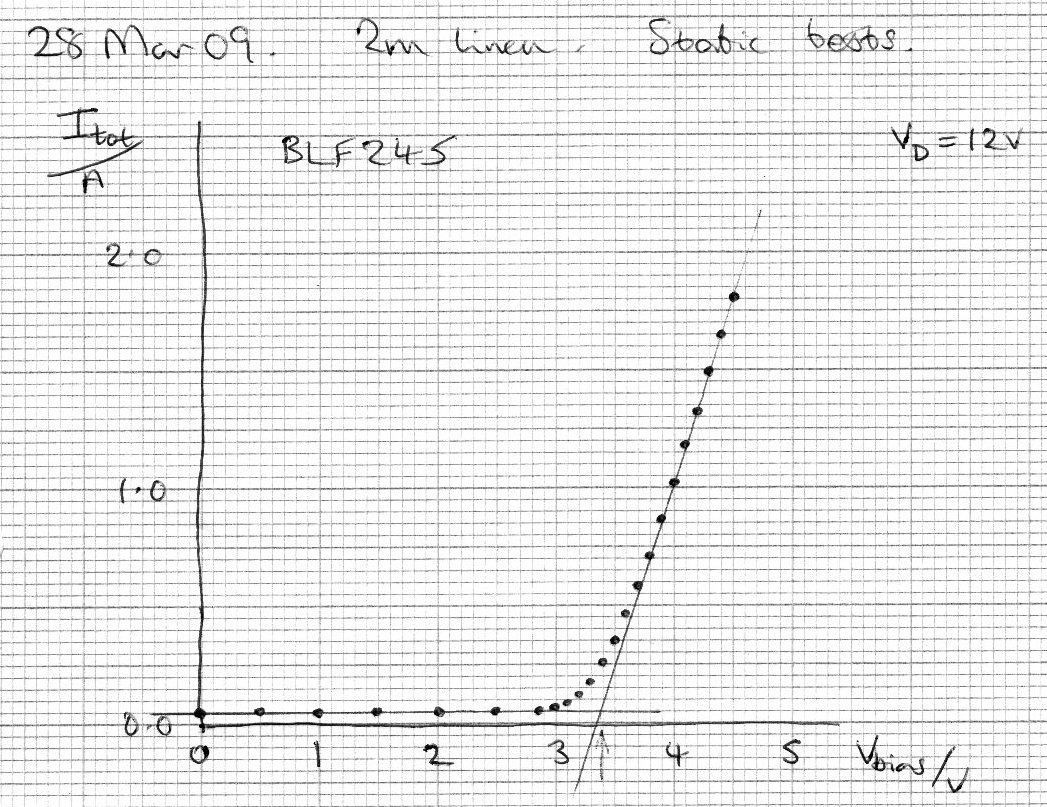
The proper RF FET is much better behaved than the switching transistors used in the HF linear! The plot below is the characteristic with a 12V supply - much more like a valve in shape, and ideal for class AB operation. At this voltage the FET doesn't get noticeably warm at all. The offset current is the 50mA taken by the bias board and switching relay when PTT is on (that turns on the bias). With PTT off, the whole circuit only takes about 10mA.
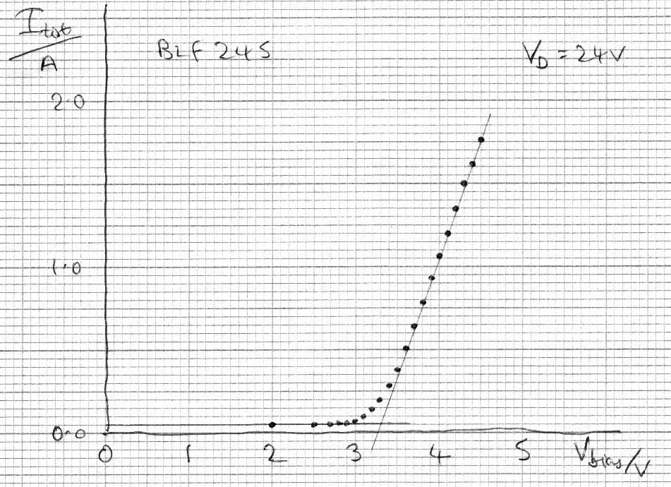
With 24V applied from two SLABs, the first effect was a 'crack' and the smell of fried electronics, so the 24V came off very fast. It hadn't blown the fuse, but a supposed 35V 1µF tantalum capacitor - admittedly salvaged off some old digital card. I replaced the capacitor (on the input to the 7812) with a 4.7µF 63V electrolytic job out of the old capacitor box. The transfer characteristic is much the same as for 12V, but not quite so steep; the data sheet predicts this happens as the FET temperature rises, and indeed it was getting warm this time, sinking more than 36W continuous.
Construction - finishing off
To make sure the linear is legal we need to make sure any harmonics are at a suitably low level. To do this we need to add a low-pass filter. We also need to add the switching for transmit/receive, since manual switching would be highly unsatsfactory.
Below is the final (or at least, for the moment final) setup. The Rx/Tx switching relays are mounted on the board at the bottom of the photo (mounted on the box side), and the low pass filter on the right above the output BNC socket. Getting the switching working was not easy. It's a long time since I've built VHF stuff, and had got out of the careful grounding habits required. I just could not work out why, when I applied input power, all the relays would switch off! Clearly a signal was getting to the bias board with the main relay control on it, and I spent an hour or so sticking decoupling capacitors all over that board, with no success. Next, I decoupled the relays properly, and added some ferrite bead chokes on the power lines to the output relay. Nearly there, but still not satisfactory. Finally I tried grounding the 0V line on the switching relay board directly to the case, and all my problems vanished! So that board is grounded through one of the screws which are visible, fastening the board to the side of the box.
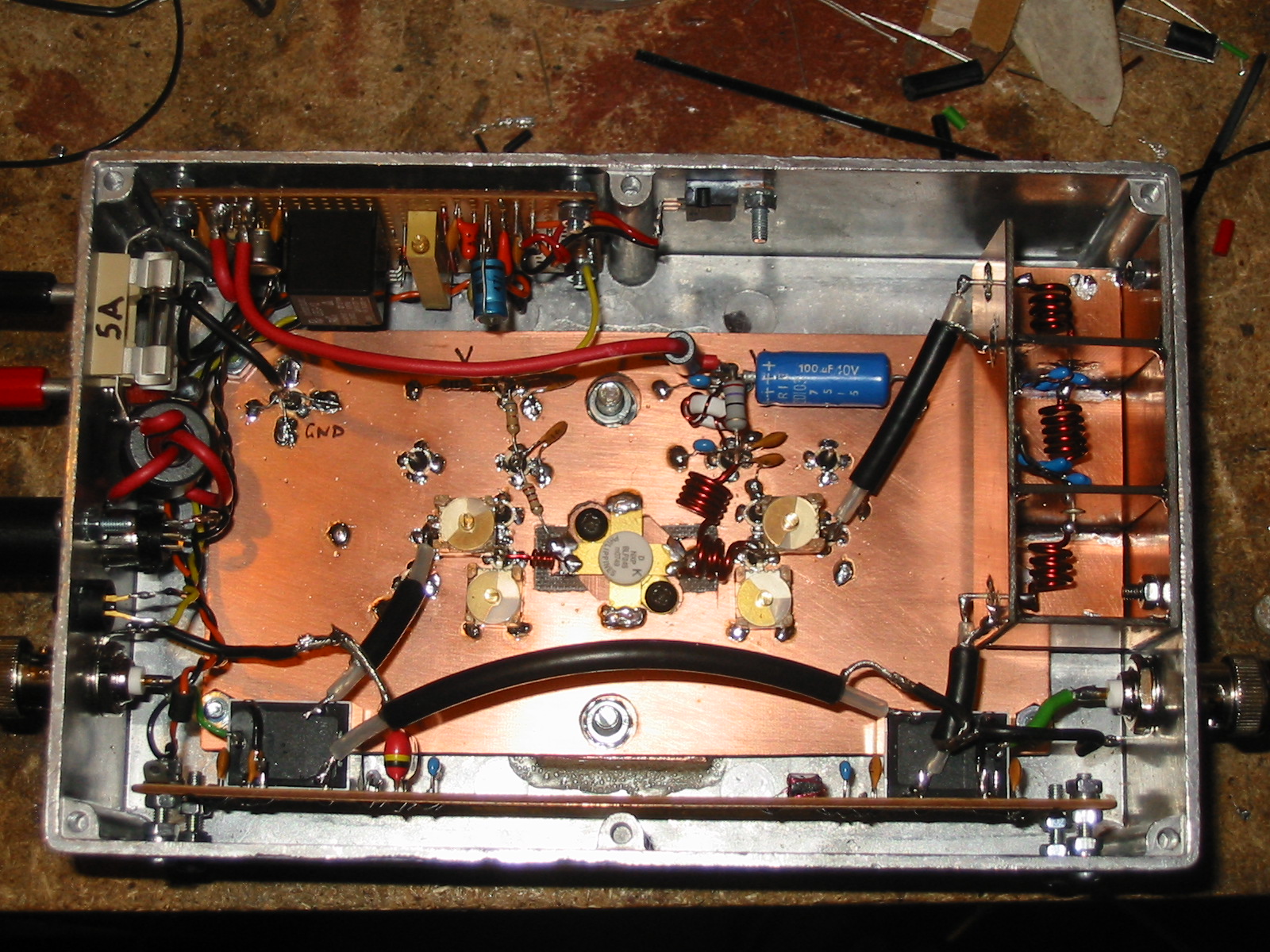
I thought all my problems had vanished; I had a nice low pass filter design from Eamon Skelton (originally Rad Com Homebrew column, June 2007) which I thought I'd be able to duplicate. I also fired up RFSim99 (put it into Google - it's a free download from all over the place, but I haven't found an original source) which is not Linux software but runs fine in Wine if you get an up-to-date version. The circuit seemed fine with the bits I found in the junk box, but once constructed and installed I was deeply disappointed to find not a lot of signal getting through it. I hadn't, of course, measured the inductance of the inductors, which eventually turned out to be the problem; I realised that a relatively small error would push the filter cutoff well below 144MHz! Measuring the coils carefully, I found that, though wound on a 5mm former (drill bit!) with 1mm wire, I assumed a diameter of 6mm to the wire centres; but the measured diameter is 6.5mm, which makes a huge difference to the inductance. So, with a new simpler filter done on RFSim99 to match components I had handy (will put the circuit up eventually) I hoped for success, and once installed, found the new design works fine. It's in the photo below.
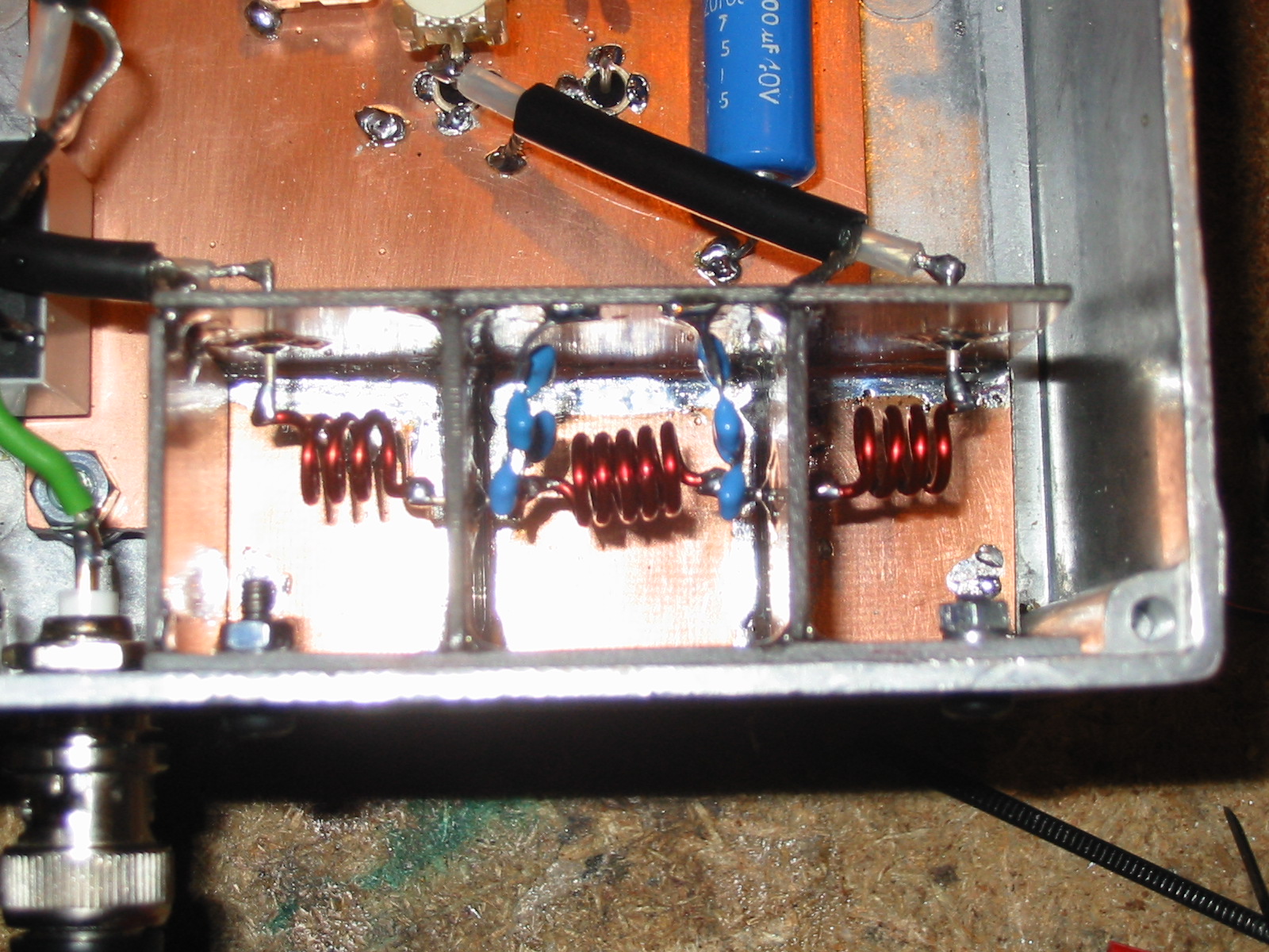
Aligning everything for final operation could now be done. On the input side, the match isn't all that wonderful with the nasty relay in the way, but I tweaked the input capacitor (leftmost trimmer in the photo below) for minimum VSWR on the FT-817. The next capacitor is not too sensitive and just needs to be trimmed for maximum power. The third capacitor is most sensitive to adjustment; the fourth is set for minimum loading consistent with maximum power output. The trimmer capacitors are reasonably robust 300V types from Farnell; certainly adequate for this reasonably QRP design.

Below is the bias board after it was splattered with decoupling capacitors. I haven't bothered to remove them as they will do no real harm. Note the pseudo-dead bug construction on the main board - the glass feed-throughs are soldered into holes in the board, to act as component mounting points. You should be able to tell that I used to build stuff with valve bases, tagstrips, etc.
Having completed the alignment, we appear to be getting about 22W of RF out of it at present, and it goes up and down with voice on SSB, so looks promising. Not quite as much power as I'd hoped, but plenty to play with for now, so it will go out with me on the next SOTA expedition to see if we can find someone willing to give me some reports on how well - or not - it works.
Circuits
The bias and control circuit is almost the same as for the HF qrp linear; it's just that the layout is much more critical, as described above. It is designed to be run off a couple of 12V SLAB batteries to give a 24V supply. Tx PTT control is taken from the FT-817 data out as before.

The PA circuit follws the data sheet fairly closely, with matching inductor values initially guessed at based on the 175MHz design in the data sheet. The capacitors used can tune it up OK. The FET is a BLF245 as noted on the characteristic curves above.

Low pass filter details
RFSim99 was used to design a 5 pole Chebychev filter with a cutoff a bit above 146MHz. This was tweaked until the design capacitor values matched something I could achieve with the capacitors I had in stock. I ended up with a cutoff at 153MHz which gives a bit of room for error. The design values for the inductors were 59.649nH and 102.724nH, and for the capacitors 28.527pF. The practical design looks like this, with the series/parallel capacitors giving me 28.5pF:
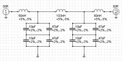
The inductors were constructed as follows and can be seen in the photo above:
- 60nH: 3.5 turns, 6.5mm diameter, 5.75mm long
- 103nH: 5 turns, 6.5mm diameter, 7.35mm long
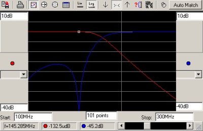
Here's the RFsim99 plot of the filter response; the return loss dips nicely at the sort of frequencies I use.
Testing it out
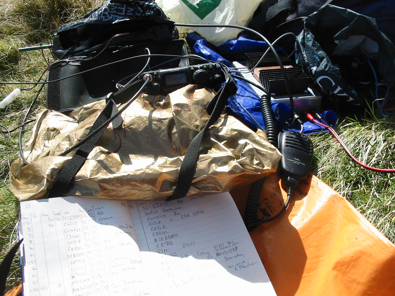
Here it is finally in use on the summit of Bengray for a SOTA activation. Everything looks a bit messy, but the batteries (12V SLAB for the FT-817, 2 × 12V SLABs for the linear) are in plastic bags - I have used plastic bags in my rucsac for ages, since things once got very wet in torrential rain.
The results seemed pretty good - much easier to make contacts down into the south of England from southern Scotland than with the FT-817 alone, even in conditions that were not particularly good. Reports on the audio quality were also gratifyingly good, so it must be reasonably linear. I think it could probably do with a preamp for receive - maybe that should be the next project (after I have got some better antennas made up for the coming RSGB Backpackers contests - not that I'm a keen contester, but they are a great opportunity to try out homebrew kit!).
Addendum - repairs!
Well I did try it out in the contest - but had a little disaster with the polarity of the battery and blew up the FET. The outcome of that was the shift to the use of powerpole connectors - see the little project about that.
However, you can read of my concern about lack of output power in the preamplifier project write-up. If you look carefully at the output low pass filter in the photo there, you can see a somewhat charred central inductor! I just didn't notice that at the time, and it's clearly the explanation of the reduced power - the capacitors in the filter must have been over voltaged and burnt out. You can see the result in the photo below, where the capacitors have been replaced by high voltage mica ones, and the inductor cleaned up a bit.
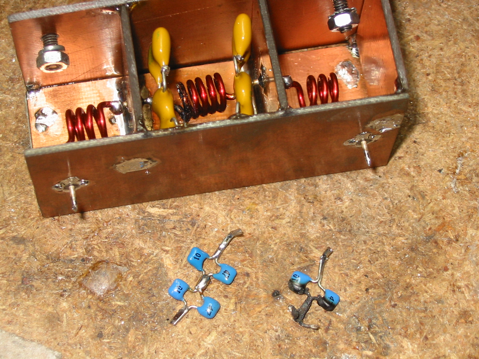
Hopefully that little problem will not happen again; and yes, I seem to have the power back!