
John's homebrew pages
RF probe
This came about as a result of need for the 23cm transverter project.
The aim of the transverter project is to see if I can build something that works for microwaves using the minimum of test equipment (mainly because I didn't have any for microwaves, never having built anything for these frequencies before).However, I was getting stuck with the local oscillator multiplier chain. I could tell there were instability problems at first (easily fixed), but once those had gone it became very difficult to tune up the chain with only the microwave RF sniffer; I needed something that would give me something I could measure properly on the oscilloscope, or at least with a voltmeter (I use the 'scope as a voltmeter probably as much as for any other purpose).
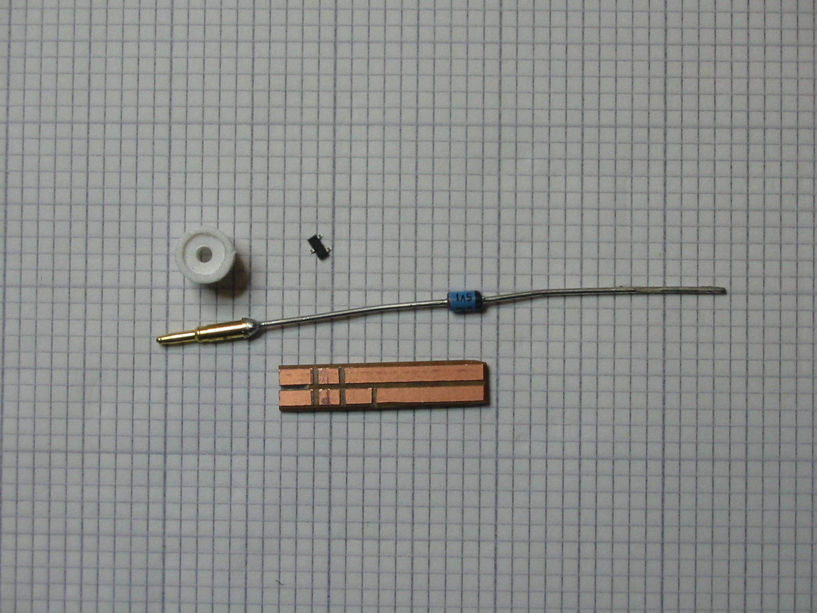
An RF probe converts the RF AC signal to DC so it can be measured; at there frequencies the conversion needs to be done very close to the sampling point since adding long wires to such circuits is a complete no-no - you let all the signal radiate away! I decided to build one (it's a standard circuit found in all the usual books but I'll add it here in due course) - here are some key bits. The probe tip is from a BNC plug, and the white insulator was extracted from the same plu with a hammer and an allen key, then the plastic shield around the pin cut off with a sharp knife. The probe tip is soldered to a zener diode, purely because it had decently thick wires to allow me to cut off one end to attach the probe tip to the pcb.
To the right of the whie insulator is a Schottky diode package, two diodes in series (see the circuit). Below is a bit of spare matrix board, from the edge of an old board where no holes were drilled. I used a hacksaw blade to cut the gaps for the components. Not in this photo are the capacitors (0603 types) and resistors (0805 types salvaged off old computer boards).
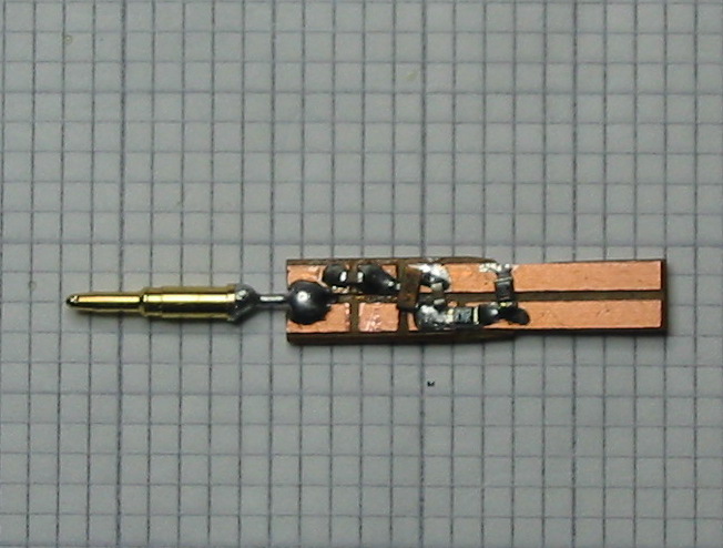
Once assembled the board looks like this. You can see the input DC blocking capacitor (top left, brown middle with silver ends); the diode package is mounted at a slight angle to fit the tracks; then there's the integrating capacitor and two resistors that have their values marked.
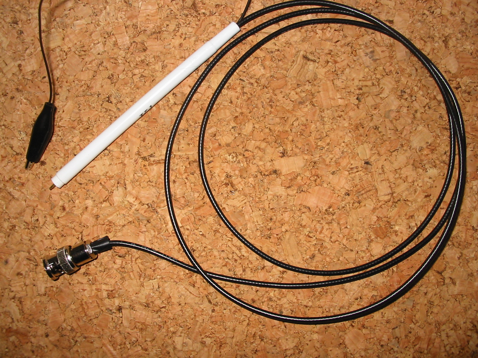
Here is a photo of the finished article which is mounted in an old "Kleeneze" free ballpoint pen! There's an earth wire with croc clip brought out from the board, and a bit of RG-174 coax with a BNC connector on the end allows us to attach it to the 'scope.
The probe works very well and has allowed me to check the drive level to the mixer on the transverter board is OK, as well as making initial alignment of the multiplier stages easier.