
John's homebrew pages
An RF sniffer for microwaves
This is another interlude. I had built the multiplier chain for the 23cm transverter, but didn't have a good way of being reasonably sure the tuned circuits are peaked up. In the RGSB / ARRL International Microwave Handbook I came across a neat little idea from W1GHZ, using a power detector chip, the LTC5508 which is good up to at least 7GHz according to the data sheet. For a display, instead of using a moving coil meter, an LED barcode display with encoder chipare used. The chip is an LM3914, as in an original LED power meter designed by WW2R and apparently available from Down East Microwave in the US.
The first step was to build and test the display. Here it is, with a rotary pot providing a variable input voltage. The display can be set as either a single moving bar (uses less power for /P) or as a variable length bar.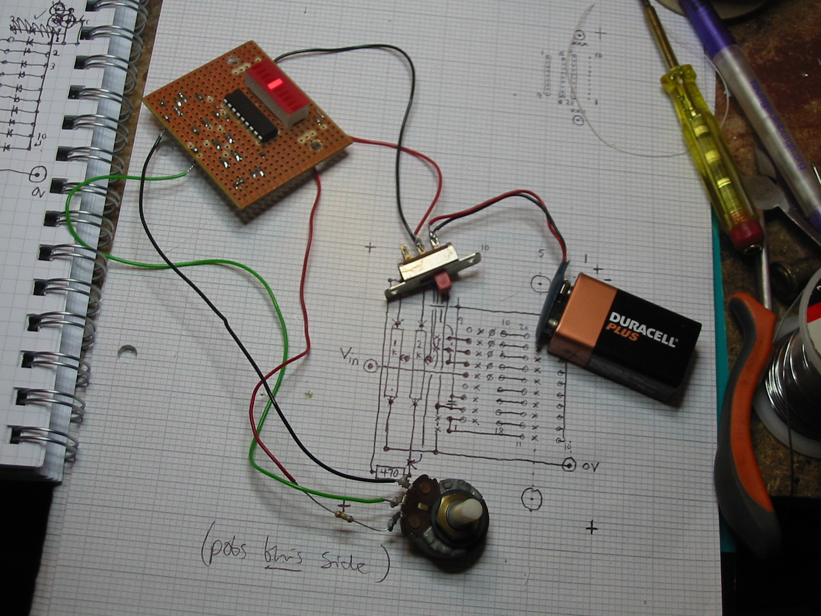
I modified the voltage range setup for the LM3914 compared with that given in the Microwave Handbook, using the data sheet information, to give a simpler layout and make use of what I had in the junk box. I'll put the circuit here eventually.
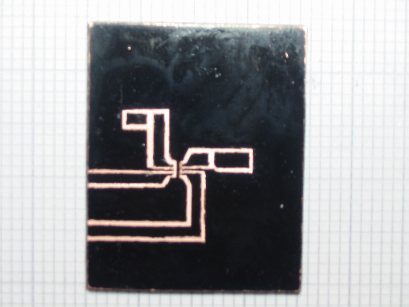
With the display working it was time to build the detector. The LTC5508 is in a SC70 package, so the whole thing is less than 2mm square. For my second surface mount project, this was a bit of a challenge, especially with a hand drawn circuit board. However, here's the board inked up:
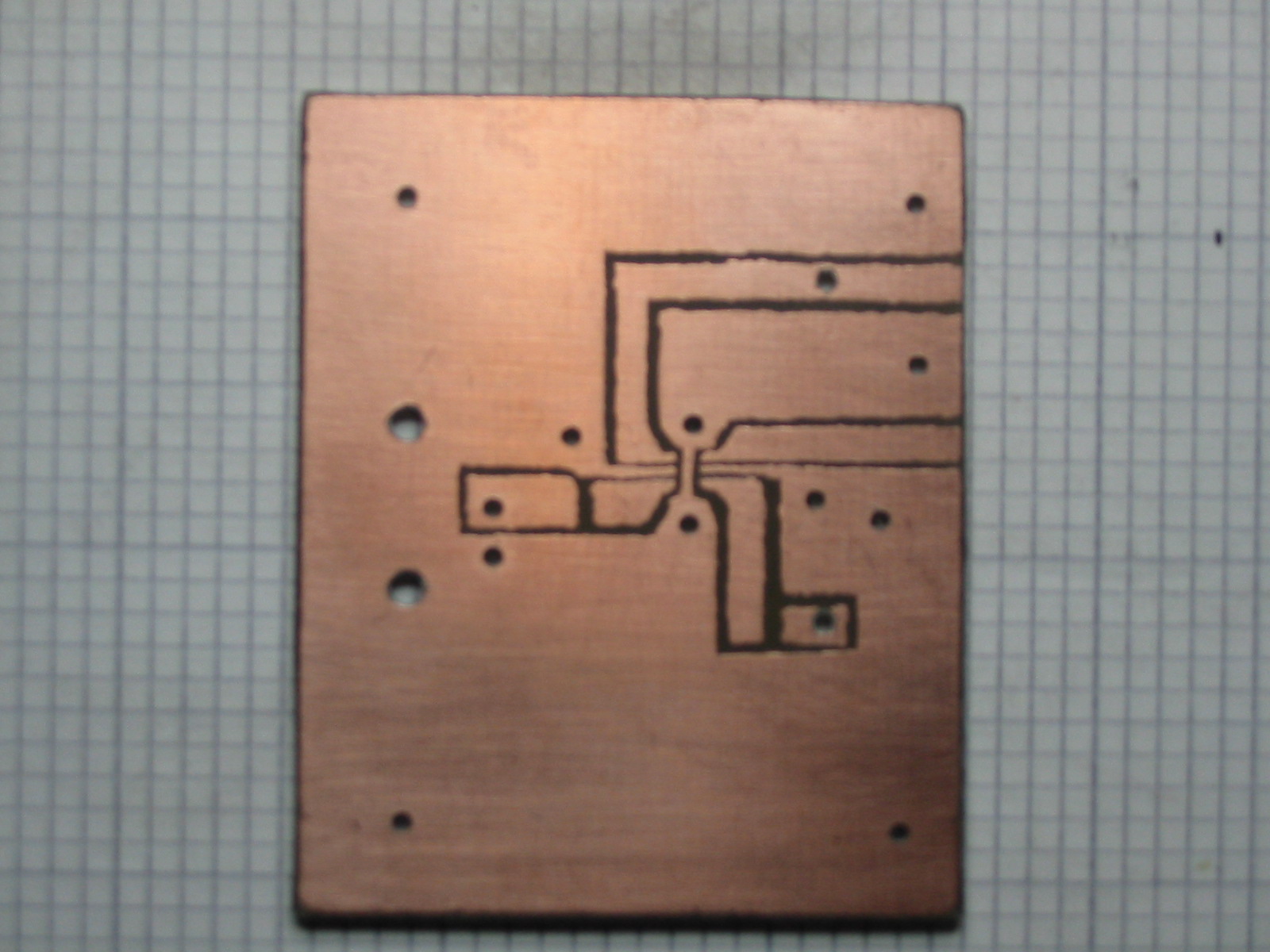
After etching it looked like this. Unfortunately these are not quite sharp, I must use a more solid stand for the camera.
All the capacitors and resistors were mounted first, and then I had the challenge of getting the chip on. I had to use a hand magnifier to be sure that I could see the mark indicating pin 1! However, with the chip set down on the board and held in place with a cocktail stick in one hand, I tacked down the SHDN pin with the other, then very carefully soldered the rest of the pins - these with an old 15W Antex iron and 1.2mm solder. A delicate job, but good practice for surface mount; fortunately I didn't bridge any of the pins with solder.
Having built the RF board it was time to see if it actually worked. There's a 5V regulator on the display board to provide power; the detector board simply returns a voltage which tells us how much power is being detected. Here it is connected up.
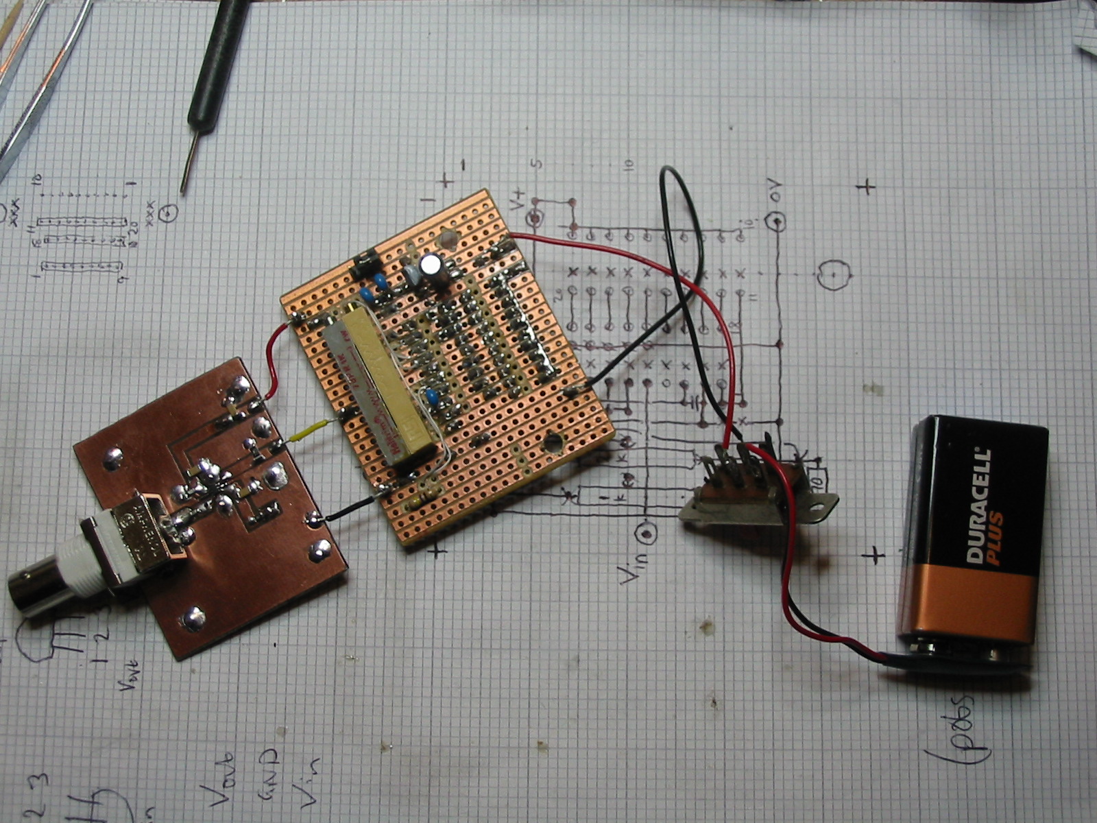
Wonder of wonders, it worked! I put 10cm of wire into the input BNC connector, and was able to get several bars of signal from the FT-817 on 70cm using the rubber duck antenna across the bench. Then I took it downstairs and fired up the microwave oven - some bars of signal there as well (through the window, not particularly near the door seals). I'll need to get a better idea of the calibration before I decide if there's too much radiation leaking from it!
Here's the RF board in closeup; the LTC5508 is the six legged thing in the middle. It's not very big.
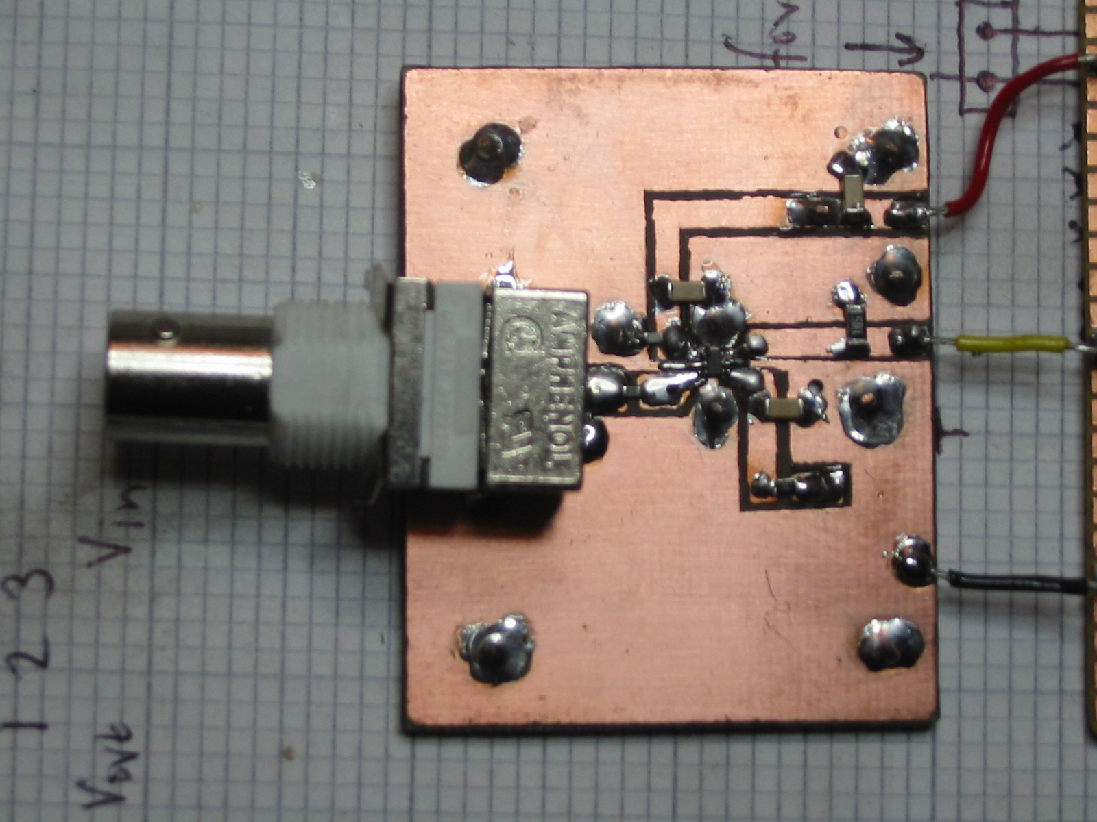
The next step was to put it in a box, which I got from Maplin for speed (there's a shop in Edinburgh). It has a battery compartment so the battery can be changed without opening the main box. I had to make a couple of brackets from PCB material to mount the RF board and BNC connector - I could do wih a 1/2 inch UNC fine nut to hold the connector firmly; it was salvaged from an old PC network card. It all fits nicely though.
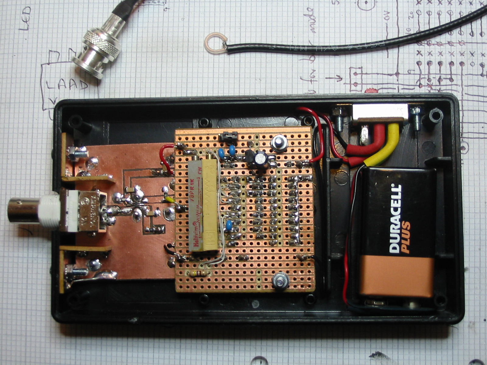
I also made a sniffer loop from small coax (RG174) and a crimp BNC plug; the loop is about 7mm diameter. More importantly, the sniffer was put into use to peak up the multiplier chain for the transverter - it's nice and sensitive, and the signal from the second tripler puts the detector off scale! I'll also see about getting a better idea of its calibration, and probably add a jack to allow the use of a DVM to measure the detector output voltage more accurately.