
John's homebrew pages
Microwave wavemeter
This is another sideline that came about as a result of need for the 23cm transverter project.
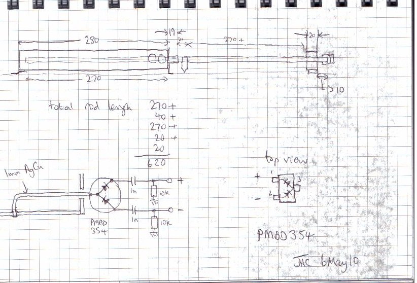
For quite a while I've thought that I ought to build a wavemeter, and there's a design which appears in the old RSGB VHF/UHF Manual (3rd edition, 1976) on page 10.40 and is repeated in the current RSGB/ARRL International Microwave Handbook (2nd edition, 2008) on page 280. I thought I had the transverter nearly finished, then discovered that the Tx side was oscillating (RF still detected when no drive applied!) so I thought a bit of "back to basics" was needed. About the same time Jon GM4JTJ got in touch and sent me some very encouraging words, with a recommendation for a "sludgepump" type wavemeter, which is exactly what that design is. Thanks to Jon for further details and for the encouragement. Here's the result.
Drawn up, this is the basic design:
We really are getting into plumbing here. A length of 26mm i/d copper pipe seemed the ideal line, rather than having to make a trough (and anyway I had some pipe in the loft). The problem was going to be soldering stuff together; even with a powerful soldering iron it's a bit tricky. So I went the whole hog; last time I did any plumbing with soldered joints it was with a borrowed gas torch, so I have now bought a "microflame" gas torch which is ideal for this sort of work (and is going to be very useful when I start using waveguide). Great care is needed, of course, to work with a flameproof background etc., but it's a great tool.
Here's the "jig" used to hold the BNC connectors in place for soldering:
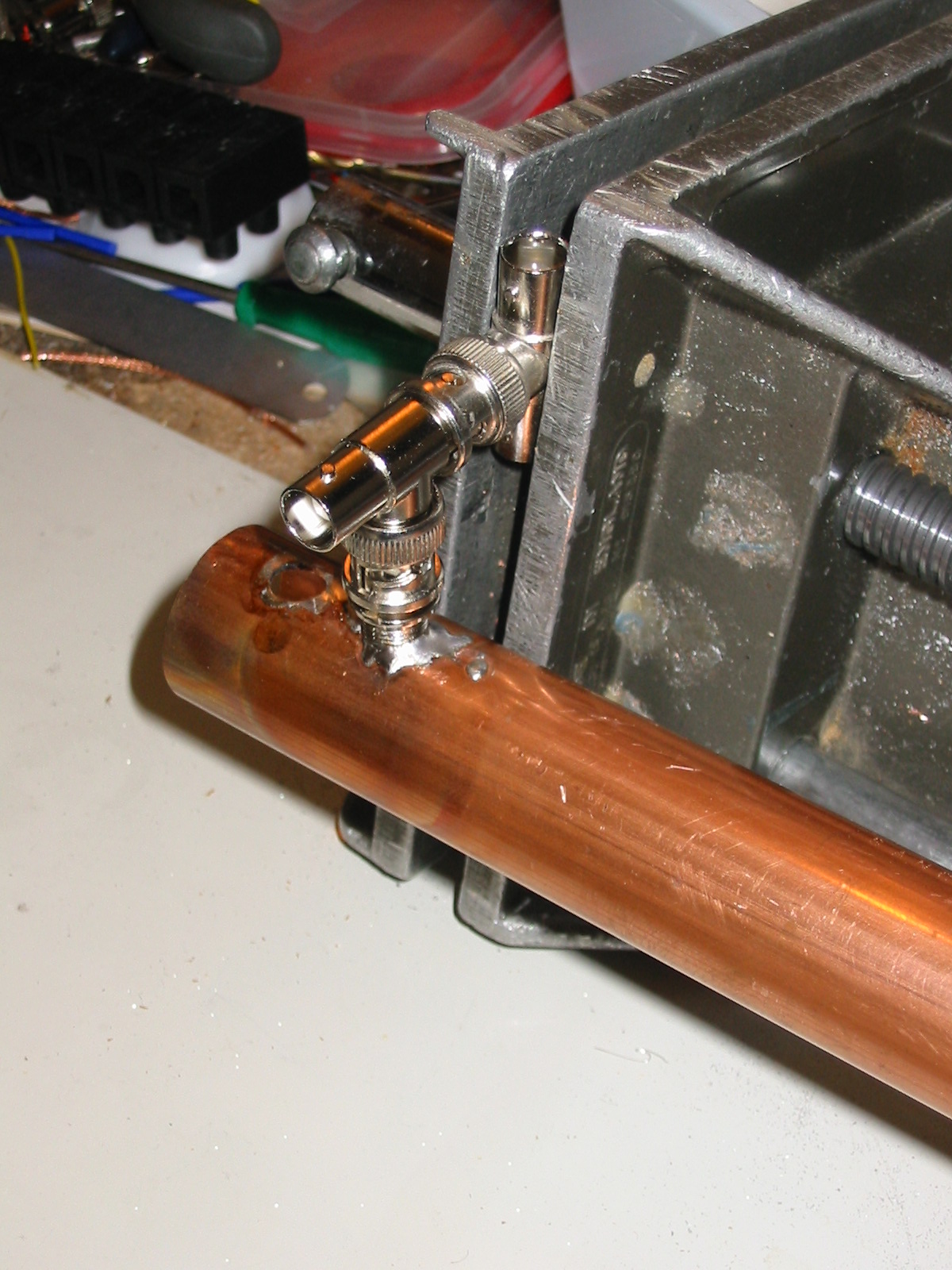
Once both BNC connectors were soldered in, I could fit the input coupling line, made from a bit of copper flattened from some tubing. You can see it in the following photo.
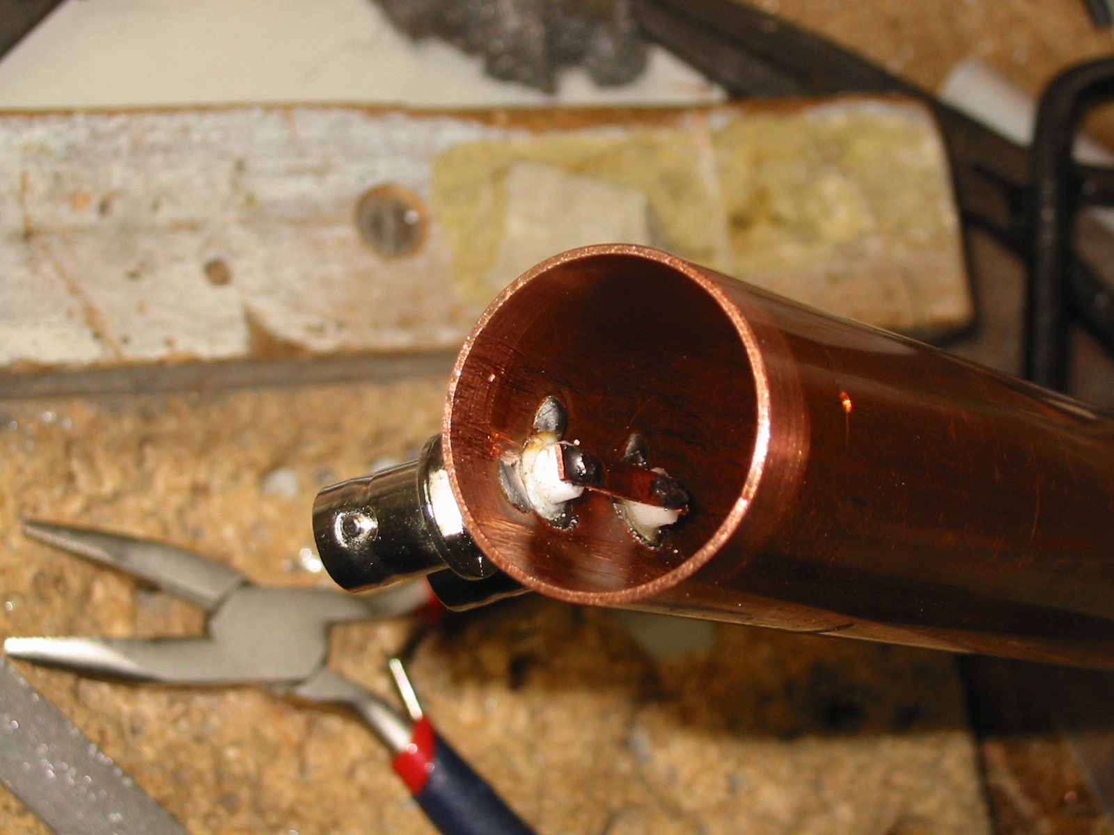
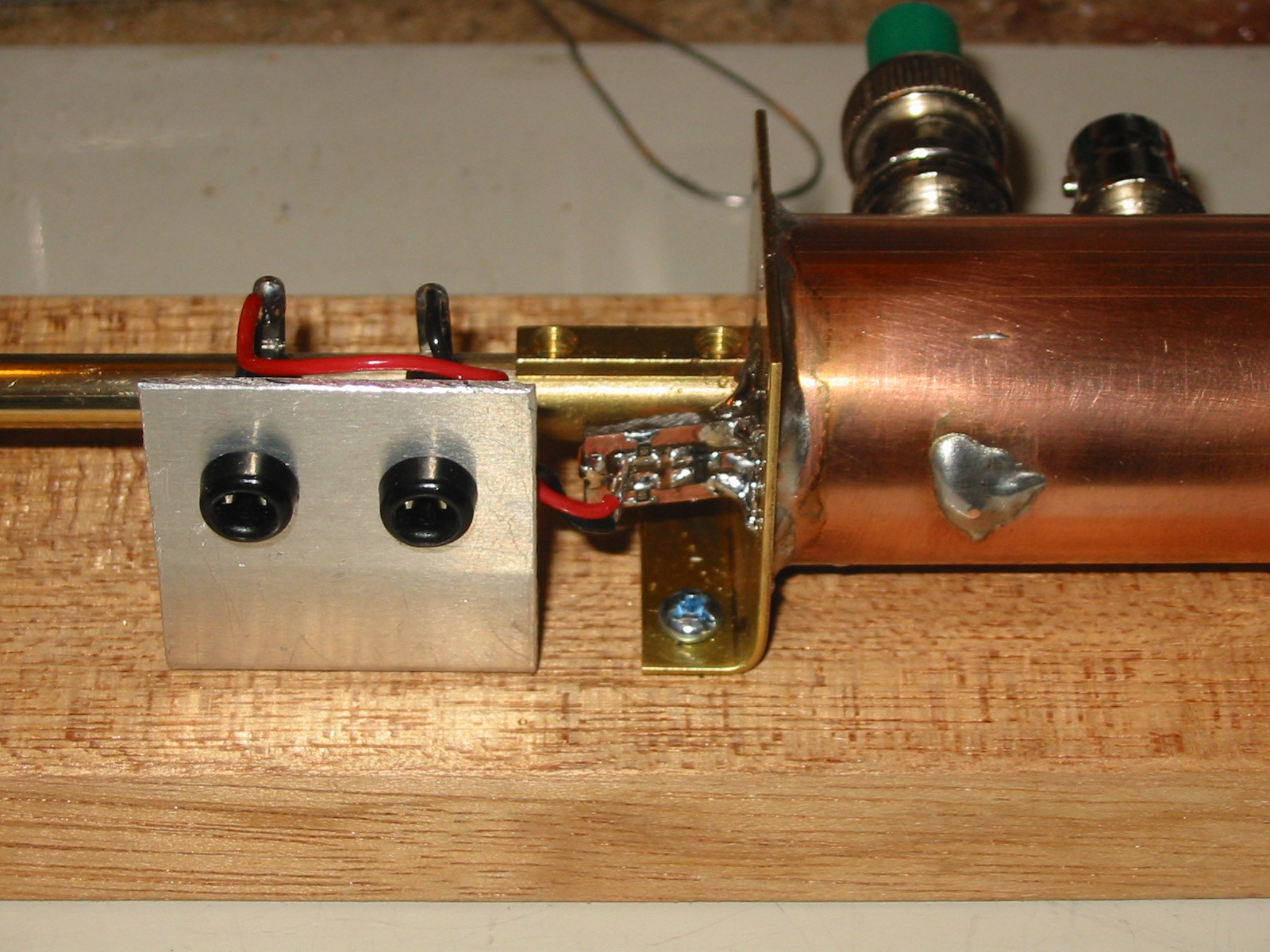
The detector loop (1mm silvered copper wire) was also soldered in before fitting the end plate; the hole for it can be seen in the photo above, opposite the BNC connectors.
Here's the jig to hold everything in place for soldering the end plate, which already had the resonator mounting attached, and a hole drilled (and pre-tinned!) for the detector output.
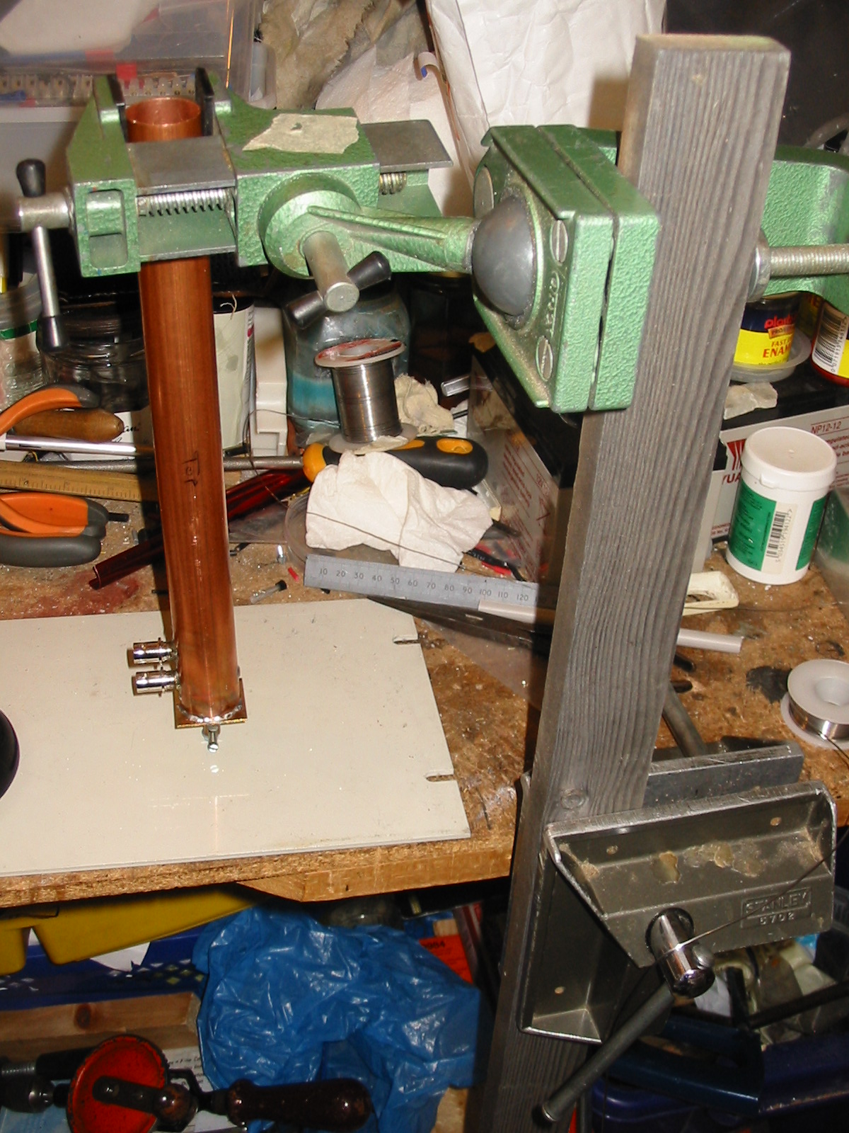
The resonator is a piece of 6mm solid brass rod from B&Q, and I fortunately found an old brass fitting from something ancient and electrical which had a hole just about the right size; a bit of extra drilling with a 6mm bit made it an excellent fit. This fitting is soldered to the endplate, and can be seen in the photo below. The detector loop comes out through a hole in the endplate, and is soldered onto a tiny circuit board which contains a double Schottky diode detector (circuit is in the drawing above), two 1nF capacitors and two 10kΩ resistors. The outputs go to the black wander sockets.
Here's the whole assembly with a meter attached. The brass rod has a knob fixed to make adjustment easier, and there will be a scale and pointer where the extended part of the rod is, to the right of the connectors - you can see a ruler placed there for initial measurements.
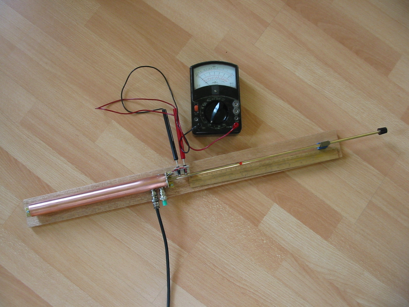
This is clearly a great device - it certainly works, with some 70cm input from the FT-817 there's a really sharp peak in the response at resonance. So it's now ready for calibration. I'll probably add a bit more once that's been done.
I have another bit of test gear that I'd started - a milliwattmeter - and that will go very well with this device, to make a sort of mechanical spectrum analyser. It certainly looks like a bit of Victorian engineering - the base is a bit of teak left over from when the kitchen was done, so I'll maybe even varnish it!